As broadcast plants have been converted to digital during the past decade, there have been many changes. Often, this change has been subtle or incremental. In some cases, adding equipment such as nonlinear editors, file-based ENG camera systems, content servers, STL, or DTV transmitters has required broadcasters to "re-learn" the trade.
While the term "RF transmission" means the same thing it always has, DTV has changed the way content is placed into that transmission. Consequently, the face of the DTV transmission is completely different from its analog cousin. This is true with COFDM, 8-VSB, or any other digital modulation scheme.
Unlike analog TV broadcasts, DTV signals are measured in average power. According to Bird Electronics, a leading RF measurement equipment manufacturer, old style diode detector RF meters are just not accurate with the high peak-to-average power ratios found in DTV, and such errors can make it difficult to do power measurements. For DTV transmissions, full-wave diode (or "square law") detectors appear to be the latest trend. These provide ease of use, along with accuracy approaching, or exceeding, that of a calorimetric system.

The Bird Electronics BPME/BPM 3129 power monitor RF power monitoring systems not only need to be accurate, but they are expected to be stable and trouble free as well, since many engineering departments have shrunk over the years. Further, we live in a connectivity-based world, and broadcasters have come to expect remote monitoring from anywhere on the globe.
The Broadcast Power Monitor (BPM) 3129, along with the Broadcast Power Monitor—Enhanced (BPM-E) from Bird Electronics makes a powerful combination for any transmission facility. IP connectivity provides accurate site monitoring from anywhere in the world.
FEATURES
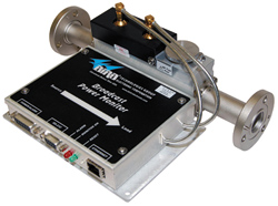
The BPM-E is a coaxial power monitoring unit that can operate in conjunction with the Bird's BPM 3129 rackmount display for local operation power and information display, or as a standalone Ethernet-based monitoring system. The BPM-E is available for VHF and UHF, with power capabilities of up to 75 kW. The sensing unit mounts inline with the transmission plumbing, and is approximately 5 x 6 x 1.75-inches, while the BPM is a 1RU rackmount package. The specified operating temperature range is 14 to 122 degrees F, and in conditions of up to 95 percent humidity (non-condensing). Accuracy is stated as five percent for RF power and 10 percent for VSWR. (Annual calibration is required for optimal performance.) Data connectivity between the BPME and the 3129 is provided via a supplied cable. Alarms for VSWR, No/Low Forward Power, and High Forward Power are programmable, and relay contacts are provided. Being IP-based the BPM-E can also send out alarms via e-mail and text messaging.
The BMP-E sensing unit comes mounted on a length of transmission line ordered to your specifications. The lower side contains all of the connectivity, including a DB-15 connector for Pwr/Alm, a DB-9 for serial connectivity, an "alarm" LED, a "power" LED, a "reset" button and an RJ-45 connector for Ethernet connection. The upper side of the unit has a "3rd Socket" for use with an optional sampler for special applications where spectral emissions performance is mandated.
The front of the BPM 3129 contains the power switch, a large four-digit forward and four-digit reflected power LCD display, a "Mode" switch, a "Units" switch, alarm LED, reset button and remote DB-9 connector. The rear of the unit sports a power connector, and a number of connections to relay contacts. BNC outputs are provided for external metering, with each providing 2 VDC at full scale power (1/10th full scale for reflected). The output level is linear with respect to power. For alternative alarm connectivity there's a DB-15, and a DB-9 providing linkage to the BPM-E.
IN USE
As an initial check, I decided to power up the two units before breaking my transmission line to install the sensing device. As with most IP-based products, my first priority was to get the units talking and establishing connectivity with my laptop computer. I connected the Data/Power cable between the 3129 and the BMP-E and with application of power the units came to life. Next came PC connectivity.
I loaded the Bird applications provided onto my laptop and connected a "crossover" cable between the BMP-E and computer. However, this led nowhere and after exhausting a lot of possibilities, I decided it was time to call Bird. After a brief chat with their help desk and also some assistance from our friendly in-house IT expert, I was able to establish connectivity. I guess I'm getting old, but I still get excited when one piece of equipment connects to another via Ethernet.
With both units and my PC happy, it was time to let them do what they were designed to do—measure RF power levels. For test purposes, I decided to use our Channel 32 UHF DTV transmitter as a power source, terminating it into a Bird 1,500 W test load. The transmitter is a solid-state Harris Ranger equipped with a CD-1 exciter with a maximum TPO of 500 W. Connectivity is via a 7/8-inch hardline. After patching in the "dummy load," and with all breakers turned off, I broke the transmission line to install the BPM-E.
With all flange hardware tightened to spec (and with the hardware threads pointing the proper direction with respect to the RF flow), I applied AC power to the Ranger chassis, reviving the unit and then brought the touch screen GUI to life for the first time in months. After giving the unit a few minutes to warm up (old habits die hard), I hit "plates on" for the transmitter. All indicators came up "green," and power read about 154 W, according to the GUI power display. Looking at the 3921 display, it indicated 156 W, with zero VSWR. Things appeared to be on the right track. Checking my laptop revealed that I did indeed have a power reading of 156 watts on the Web-based display. As I raised the power level on the transmitter, the readings displayed on both the Harris GUI and the Bird system never differed more than one or two percent. Even when approaching 500 watts, the units were within three watts on their readings. Obviously this was not a lab quality accuracy test, and that was not really my goal. My observations are from a user's point of view; not that of a lab.
The display on the 3129 is very straightforward—the only options are units (W/dBm) and mode (%/dBm); however, using the "Virtual Meter" display on the PC is a different story. As with most I-based systems, there are many features and options.
BPME Finder is an included application that allows searching the "Network" for active Bird units. It will provide the address of any Bird units it finds, so you can type them into your browser for access. This application was most useful to me, as I operated in dynamic host configuration protocol (DHCP) mode. However, for configuration in permanent locations, DHCP should probably not be used, but for ease of connectivity, I decided to stay in DHCP mode.
For Ethernet connectivity, Bird's browser-based Broadcast Power Monitor Web Tool provides monitoring and connectivity. Once the IP address is established on the BPME, simply typing in the address on your browser brings up the application display. It has five menu tabs, the first of which is Main which gives values for Forward and Reflected Power (in both watts and dBm), VSWR, Return Loss, RHO and Efficiency. In addition, a nice graphical meter is displayed, which can be dedicated to Forward or Reflected Power. And there's an "Alarm Condition" window with threshold settings displayed to the right side. The next menu tab is "Stats." This window is where you can select parameters to be logged and set up what type of chart you want the data displayed on, as well as the length of data collection (in days). Lower on the menu tab is "Config" where you manage alarm settings such as enable, VSWR trip, Threshold, alarm testing and latching. Located under the Config tab is also the "Frequency" tab. This screen displays configuration frequency, operating range, and allows selection of channels. The next menu tab is "Admin", which has four sub tabs. The "Network" tab is where Ethernet connectivity is managed, the "E-mail Alerts" tab is where alarm status e-mail distribution is managed, the "SNMP" tab allows alarm status distribution configuration for SNMP delivery, and the "Passwords" tab is where access security is managed.
SUMMARY
I allowed the unit to operate for several days and there were no errors or lockups. The BPME RF monitoring tool certainly lives up to Bird's reputation. The unit is solidly constructed and Bird quality is evident at every level. Setup was easy and straightforward and operation of the Web-based application was intuitive and simple.
In this time of complexities and emerging technologies, it's a pleasure to see a modern tool that embraces traditional common sense with respect to operation and control.
Joey Gill is chief engineer at television station WPSD in Paducah, Ky. He has been with the station for 25 years and has worked in broadcasting since 1977. He may be contacted atrespond2jgill@yahoo.com.
The professional video industry's #1 source for news, trends and product and tech information. Sign up below.
