Digital video basics
Digital video is best defined as a means of describing the continuous analog video waveform as a stream of digital numbers. There are several advantages in using digital video equipment:

Figure 1. Block diagram of a typical black box digital device. It can represent any digital device in use in a teleproduction facility. Click here to see an enlarged diagram.
- A digitized video signal is immune to analog signal impairments such as linear distortions, nonlinear distortions and noise beyond the inherent distortions generated by the analog-to-digital and digital-to-analog conversion process. This can fully be realized by processing and distributing the signal in digitized form.
- Digital video equipment can perform tasks efficiently and economically that are difficult or impossible to perform using analog video technology.
- Digitized video signals are amenable to the application of techniques for retention of essential information such as compression.
Historical background
The 1970s witnessed a major revolution in television studio operations brought about by the use of digital video technology. Early digital technology was restricted to so-called digital black boxes. A digital black box is a device that has analog input and output ports and performs an essential signal processing task by using digital technology. Among the early digital black boxes were time base correctors, frame synchronizers and standards converters.
The 1980s witnessed the emergence of digital videotape recorders based on CCIR recommendations. A variety of digital black boxes, such as digital video effects (DVEs), graphic systems and still stores, operating in a variety of non-correlated and incompatible standards also became available. Digital interconnections between various digital black boxes were thus difficult or impossible.
The majority of these black boxes were interconnected with the rest of the analog or digital equipment using analog input/output ports. The user was generally unaware or uninterested in the digital incompatibility of the black boxes as long as they performed their intended task and could be interconnected with the rest of the equipment. Compatible digital video equipment was assembled into a digital island, such as an editing suite, using a bit-parallel digital video interconnection.
The 1990s were characterized by an intense standardization activity led by the SMPTE. A large variety of video production, distribution and recording equipment with standardized bit-serial input/output ports has become available, allowing the assembly of all-digital teleproduction facilities using bit-serial signal distribution and interconnection.
Get the TV Tech Newsletter
The professional video industry's #1 source for news, trends and product and tech information. Sign up below.

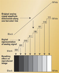
Figure 2. Graphic illustration of quantizing effects with three bits per sample. Click here to see an enlarged diagram.
The typical black box device
Figure 1 shows a simplified block diagram of a typical black box digital device. It can represent any digital device in use in a teleproduction facility. The input is a conventional analog video signal. This signal is band-limited by a low-pass (anti-aliasing) filter and fed to an analog-to-digital (A/D) converter, to be converted into digital form. This block is usually called a coder. The A/D conversion involves three steps:
- Sampling of the analog signal at a constant rate.
- Quantizing the sampled values.
- Coding the signal.
The digitized signal is fed to a digital processor, which may be anything the designer wishes. In a time base corrector, the processor performs a time base correction in the digital domain. In a video recorder, the processor records and plays back the video signal in digital format. The processed digital signal is applied to a digital-to-analog (D/A) converter. The output of the D/A converter is fed to a low-pass (reconstruction) filter, which removes high-frequency spectral components and allows only the analog video signal to pass.
This block is commonly called a decoder and changes the output of the device back into a conventional analog format. The digital black box can be inserted into a conventional television operation, and the operator need not know that the signal is being processed internally in a digital manner.
The sampling of the signal
The sampling rate of video signals has evolved through the years. Analog composite video signals are sampled at a multiple of the subcarrier frequency. Early equipment used a sampling frequency of 3fSC resulting in, nominally, 10.7MHz for NTSC and 13.3MHz for PAL. The SMPTE standardized sampling rates are 4fSC resulting in, nominally, 14.3MHz for NTSC and 17.7MHz for PAL. These higher sampling frequencies ease the requirements for the anti-aliasing and reconstruction filters and provide a better frequency response.
The frequency modulation of the SECAM chrominance carriers makes it impractical to sample the composite color signal. SECAM signals are decoded into analog components, which are digitized separately. Analog component video signals are sampled at a multiple of the horizontal scanning frequency fH.
The quantizing of the sampled values
There is an infinite number of shades of gray, ranging from black (the lowest video signal amplitude) to white (the highest video signal amplitude) that the analog video signal can represent. When the analog data is converted into digital data, some problems arise.
This is due to the fact that the instantaneous sampling pulse amplitudes can be represented in the digital domain by only a limited number of binary values (steps). This process, called quantization, results in a limited number of shades of gray that the system can resolve, depending on the number of bits used. The possible number of shades of gray is equal to 2n, where n is the number of bits per sample.

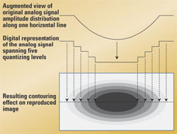
Figure 3. Graphic illustration of contouring effect resulting from quantizing errors. Click here to see an enlarged diagram.
Figure 2 shows what would happen to an analog video signal known as “horizontal ramp” when an insufficient number of bits per sample is used. Normally, the ramp signal is displayed on a CRT screen as a smooth transition from black, at the extreme left of the screen, to white, at the extreme right of the screen. When sampled and quantized, in this hypothetical case with a precision of three bits per sample, the ramp can only assume eight “quantizing levels” (23=8).
The displayed picture features eight brightness levels ranging from black (digital signal value 000) to white (digital signal value 111). The reproduced image is clearly a distorted representation of the original because the quantizing process introduces “quantizing errors” (Qe), which are inevitable.
It is evident that an acceptable digital representation of a video signal requires more than three bits per sample. Experiments have shown that using less than eight bits per sample results in a distortion known as “contouring.” Figure 3 on page 17 shows the effects of contouring on a CRT displayed picture. In this example, the brightness of the original picture varies smoothly from left to right and from top to bottom with a reduced brightness at the center of the picture. The system can only recognize five brightness levels resulting in patches of uniform brightness (contours) separated by sharp transitions. The eye is more sensitive to contouring effects at low picture brightness levels. With eight bits per sample, or more, the quantizing errors appear as random noise in the picture.
The number of quantizing steps, and, consequently the magnitude of the quantizing error, depends on the number of bits per sample. Early technology used seven or eight bits per sample, depending on the class of equipment, resulting in, respectively, 128 or 256 quantizing steps. With few exceptions, contemporary studio-type equipment uses 10 bits per sample, resulting in 1024 quantizing steps and excellent picture quality.
Michael Robin, a fellow of the SMPTE and former engineer with the Canadian Broadcasting Corp.'s engineering headquarters, is an independent broadcast consultant located in Montreal, Canada. He is co-author of Digital Television Fundamentals, published by McGraw-Hill, and recently translated into Chinese and Japanese.
Send questions and comments to:michael_robin@primediabusiness.com
The Second Edition of Michael Robin's book may be ordered directly from the publisher's Web site atwww.mcgrawhill.comor from Amazon atwww.amazon.com. The book is available in both English and Japanese.
