Integrating fiber optics

Use of fiber-optic technology in broadcast infrastructures is increasing at an overwhelming rate. Equipment manufacturers are including fiber interfaces for SDI and network connections in new equipment; routing systems are using optical switching matrices in their latest 3Gb/s generation of products; and SMPTE 311, hybrid fiber-optic cables are replacing triax for cameras.
Until recently, fiber-optic technology has been significantly more expensive than a copper equivalent, placing it out of the financial reach of many new systems. But widespread deployment by the telco industry has brought the price down.
Today, two- and six-strand fiber cable prices are on par with the broadcast industry workhorse 1694A coaxial cable. It is time to evaluate fiber technology as a cost-effective alternative to coax.
Signals, fibers and cables
Fiber-optic systems consist of a light transmitter, LASER or LED; an optical medium, glass or composite; and a photodetector receiver.
A variety of light-emitting technologies are used in transmitters: Fabry-Perot lasers or distributed feedback (DFB) lasers are used in long-haul and high data-rate applications; vertical-cavity surface-emitting lasers (VCSELs) are suitable for shorter-range applications such as GigE and Fibre Channel; and light emitting diodes (LEDs) are used for short to moderate transmission distances. LEDs are the least expensive transmitters but have limited data capacity.
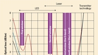
Figure 1 shows the improvement over the last few decades of fiber-optic wavelength windows. Appropriate transmitter technology is also indicated for each window.
Get the TV Tech Newsletter
The professional video industry's #1 source for news, trends and product and tech information. Sign up below.
Two types of photodetectors, avalanche photodiode (APD) and positive-intrinsic-negative (PIN), convert photons of light to electrons. Because of the small number of photons received, amplification is necessary to recover data and produce a usable signal. APD amplification is internal, while the amplification is external for PIN detectors.
Fiber-optic systems use a variety of signal multiplexing techniques. Time-division multiplexing (TDM) assigns data packets to time slots and is used in long-haul infrastructures, while wave-division multiplexing (WDM) enables multiple wavelengths of light to share a single fiber. In first-generation deployments, WDM technology supported just two wavelengths, also referred to as “lambdas,” usually 1310nm and 1550nm.
As fiber-optic technologies improved, it became possible to transmit more than two lambdas simultaneously over a single fiber strand. This resulted in the development of coarse wave-division multiplexing (CWDM) and dense wave-division multiplexing (DWDM). CWDM spaces channels 20nm apart, while DWDM uses narrow channel spacing, frequently 0.8nm or 1.6nm. Figures 2 and 3 illustrate implementations of each technique as specified in ITU-T standards.
Single-mode fiber (SMF) carries a single wavelength of light and is suited for long runs, such as between buildings, venues and broadcast sites (STL, TSL, intra- and intercity links), and as risers in facilities. SMF cables are yellow, and the fiber cores are 8.5µ in diameter. Something of an oxymoron, SMF is best suited for DWDM implementations. This is because DWDMs pack multiple lambdas so tightly that the bundle can be transmitted as a “virtual single” wavelength.
Multimode fiber (MMF) can carry multiple wavelengths on a single strand. They are used in short runs generally inside a building and are orange. The thicker core, 50µ or 62.5µ, supports the wide bandwidth of CWDM.
Single-mode fiber technology is more expensive to implement than multimode. Lasers must be precisely tuned and cannot use the less expensive LED transmitters found in CWDM links.
Making a connection
Optical fibers require precise connectors. Two techniques currently are in widespread use: angled physical contact (APC) and ultra physical contact (UPC).
APC connects 8-degree cut fibers and is appropriate for high data-rate SMF links. UPC fibers have a rounded finish that allows fibers to touch on a high point near the MMF fiber core where light travels.
When cables are mated to connectors at the factory, signal loss is less than 0.2dB, the cables are ready to install, they are guaranteed, and they can be returned if defective. In comparison, do-it-yourself connector field terminations typically suffer a 0.5dB to 0.75dB signal loss, take time to install and will have to be repaired if faulty.
Installation and testing: Handle with care
Installing and testing optical networks requires adherence to a long list of recommended practices.
Cables:
- Observe minimum bend radius, 20X the cable diameter under tension during pulling and 10X when not. Also observe cable pulling tension, 100lbs to 200lbs for indoor cable and upward of 600lbs for outdoor.
- Loosely fasten cable ties to avoid microbends that can degrade performance. (See Figure 4.)
- Use properly color-coded cables; place labels in easy-to-read locations.
- Stack cables no deeper than 2in in “fiber-only” cable guides.
- Safety is no accidentProper dressing in racks and risers will help prevent accidental damage. Plan for slack and patch cable storage.
- Single-mode cables should be tested after installation but before splicing or termination, and again after to confirm the cable was not damaged during installation.
Connectors:
- Keep dust caps on all connectors.
- Clean all connectors after removing dust caps and before connecting to transceivers or connectors. Solvents specifically developed for fiber cleaning are now available.
- Don't touch the terminations.
- Mate the cable and the connector as soon as possible.
- Place the dust caps in a small plastic bag and tape inside the cabinet for future use.
Testing:
- Measure transmitter power, receiver sensitivity and optical loss.
- Use tested patch cords of the same fiber type as the installed cabling with a known attenuation at the appropriate wavelength.
Safety is no accident
Working with fiber optics requires strict adherence to safety practices. Many of the hazards are not obvious. Even a microsecond of exposure to a fiber light beam can cause permanent eye damage. Never work on an active fiber.
Trimming, stripping or cutting fibers can create small glass fragments that are light enough to float in air. They can penetrate the skin and become embedded, causing irritation, and if ingested, fibers can cause internal damage.
Chemicals and solvents used in cleaning and splicing fiber optics can also be hazardous.
Safety practices:
- Workers performing splicing or termination should wear safety glasses with side shields.
- All food and beverages should be kept out of the work area. Wear disposable aprons to keep fiber particles off clothing. Check clothing for pieces of stray fiber; remove them with double-sided tape.
- Wash hands thoroughly before touching eyes, especially if wearing contact lenses.
- Read all instructional material before handling chemicals.
- All cut fiber pieces should be disposed of properly along with any used chemicals and containers. A disposable container that can be tightly closed should be used for fiber scraps.
Maintaining fiber installations
Fiber-optic networks generally do not require periodic maintenance. Inspection or maintenance can cause damage or allow dirt to get into components; however, outdoor installations are susceptible to mechanical and environmental damage and should be carefully inspected regularly.
Fiber installation documentation packages should include transmission wavelength, cable color, cable number, section length and the location of splices or terminations. The optical loss, measured during testing, should be recorded on the as-builts, and spare fibers should be noted. Power figures, both calculated and measured, along with installer contact information, should be included.
A new, improved cable
With the increased use of fiber for telco TV installations, the need arose for fiber cables that can withstand outdoor environments and tight residential installation spaces. The result is the development of bend-optimized fiber.
Specifically designed to minimize the effects of increased attenuation resulting from cable bends, bend-optimized fiber, as shown in Figure 4 on page 53, can be coiled into loops and tied in bundles with a 10mm loop radius; wavelengths between 1260nm and 1625nm are supported.
Benefits
The need for higher data rates will increase. One of the problems with coaxial cables is that as signal data rates have increased, the usable length of cable runs has decreased. Because optical fiber can support higher data rates, its use can help provide some measure of future-proofing for a facility.
Also, because fiber-optic cables are smaller in diameter, they require less cable tray space. This additional space allows “dark fiber” to be pulled during cable installation and reserved for future use.
The amount of fiber cables required for a given number of signals is significantly less than for an equivalent coax installation. For example, in campus and metro network topologies, a CDWM fiber can carry 16 HD-SDI signals over a single fiber for up to 40km. Similar reduction of cable numbers can be realized by using fiber instead of coax in broadcast centers.
With 1000ft of 1694A and 1000ft of dual-strand fiber both priced at about $300 and 1000ft of 12-fiber cable at $550, fiber deployments are viable, affordable solutions — despite the added cost for optical connectors, patch cables and skilled installation technicians.
Finally, total cost of ownership for fiber installation may be less than that of coax. An “enlightened” design philosophy should evaluate the long-term benefits of using fiber-optic technology in any new system design. BE
Phil Cianci is a design engineer for Communications Engineering, Inc., in Newington, VA.
