Measuring digital systems performance

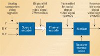
Figure 1. Bit-serial digital video signal distribution begins and ends with conventional A/D and D/A converters.
The need to satisfy complex distribution patterns typical of large teleproduction centers led to the development of the bit-serial digital signal distribution concept. This consists of reading out sequentially the 10-bit parallel data, starting with the least significant bit (LSB) and ending with the most significant bit (MSB), and sending the resulting bit-serial digital signal on a single coaxial cable. For Rec. 601, 10 bits per sample, 4:2:2 encoding this results in very high bit rates, e.g. 270Mb/s (27Mwords/s × 10 bits/word), with an associated spectrum of the order of 1GHz. A special channel coding known as scrambled NRZI (non return to zero invert) is used to randomize the data and ensure an unambiguous and error-free signal regeneration at the end of long coaxial cables, typically between 600 and 1000 feet, depending on the cable-loss equalization capability of the receiver.
Figure 1 shows a conceptual block diagram of bit-serial component video digital signal distribution. The source encoder is the conventional group of three analog-to-digital (A/D) converters, whose outputs are multiplexed into a 27Mwords/s bit-parallel datastream. The transmission channel encoder transforms the bit-parallel datastream into a bit-serial digital signal suitable for transmission by the chosen medium (e.g. coaxial cable). The signal is corrupted by the main source of interference: the thermal noise contributed by the receiver input stage. Excessive cable losses will result in a low signal-to-noise ratio (SNR) and a high bit error rate (BER). The receiver channel decoder deserializes the received bit-serial signal and recovers the bit-parallel digital video signal. The signal decoder is the conventional group of three digital-to-analog (D/A) converters recovering the original analog component video signals.
The standard interface characteristics
SMPTE 259M describes the bit-serial interface for 525/59.94 and 625/50 equipment. It has applications in a television studio using coaxial cable lengths not exceeding the amount specified by the equipment manufacturer, typically accepting a signal loss of 30dB at the clock frequency. The interface characteristics are summarized in Table 1. Figure 2 shows the typical eye diagram of the bit-serial digital signal and some significant characteristics. There are three areas of performance-related engineering concerns as follows: evaluation of equipment and technology, post-installation acceptance tests, and maintenance tests. Table 2 lists some performance-indicative parameters and their application.
Measuring transmitter-related parameters
The measurement of the transmitter output signal characteristics requires accuracy, speed and reproducibility. It is advantageous to use a digitizing oscilloscope, with a bandwidth on the order of 2GHz, that can be programmed to measure a set of parameters and display the results on the screen. The parameters to be measured are amplitude, rise time and fall time, overshoot, and jitter.
The professional video industry's #1 source for news, trends and product and tech information. Sign up below.
Figure 2. The figure shows the measurement dimensions of a typical eye diagram of the bit-serial digital signal.
The limits of acceptable performance are as per SMPTE 259M. The measurement of jitter requires the use of a suitable reference either external to the equipment to be tested, resulting in absolute jitter measurements, or derived from the signal to be measured, resulting in relative measurements. The bandwidth of the relative jitter measurement depends on the clock recovery method used, since the recovered clock signal will contain some of the signal jitter characteristics. A jitter measurement bandwidth of 10Hz to 27MHz yields timing jitter values, whereas a measurement bandwidth of 1kHz to 27MHz yields alignment jitter values. When measuring jitter it is important to mention the reference clock source.
Waveform monitors belonging to the Tektronix WFM601 family can be used to carry out signal characteristics measurements. It has to be realized, however, that these instruments have a measurement bandwidth of the order of 300MHz, which will affect the rise time/fall time and overshoot measurements results, and necessitate a correction formula to obtain accurate results. Some waveform monitors have a choice of derived reference clock bandpass, allowing the user to determine the dominant frequency of jitter. The output return loss is an important performance-indicative parameter, especially for relatively short cable runs. Special network analyzers are used to carry out this measurement. Bit-serial digital video equipment, especially large-capacity routing switchers, may generate high levels of electromagnetic radiation (EMR). Equipment design and safe installation practices help reduce EMR to acceptable levels. EMR levels in equipment and installations are measured using a calibrated antenna and a spectrum analyzer.
Table 1. Transmitter and receiver characteristics for bit-serial interfaces are summarized above.
Measuring receiver-related parameters
In addition to the input return loss, there are several additional receiver characteristics that need to be measured. These have to do with the ability of the receiver to extract the original data from a noisy and jittery input signal. Two special test signals have been developed to meet this requirement:
- The EDH test signal: The Error Detection and Handling (EDH) concept was developed by Tektronix and issued as a SMPTE Recommended Practice, RP 165. It is based on making cyclic redundancy check (CRC) calculations for each field of video at the serializer and at the receiver. The CRCs are recalculated at the deserializer and, if they are not identical to the transmitted values, an error is indicated. The EDH is used as an in-service test to pinpoint automatically and electronically any system failures.
- The pathological test signal (SDI check field): The fundamental idea behind the test signal is to stress the transmission channel and assess the effects. Sony has developed two special test signals for stressing the bit-serial receiver. One of them, consisting of a one followed by 19 zeros, has a large DC content and is used to stress the cable-loss equalizer. The second stress signal consists of an identical sequence of ones and zeros repeated every 20 bits, which provides a minimum of crossings for clock extraction. SMPTE RP 178 describes a recommended pathological test signal called serial digital interface (SDI) check field, consisting of one-half field of each of the two stress signals described above. This test signal is fed to the input of the equipment under test and the output is monitored on a color monitor. Bit errors affecting the top of the picture are a result of the malfunction of the equalizer, usually because of a coaxial cable length in excess of the equalizer correction capability. Shortening the cable will eliminate the problem. Bit errors affecting the bottom half of the picture are caused by a malfunction of the receiver clock regenerator and could indicate a condition where the free-run frequency of the PLL-controlled VCO in the receiver has drifted from the specified frequency. A readjustment of the VCO frequency will eliminate the problem.
Table 2. Performance-indicative parameters are used for the evaluation of equipment and technology, and in post-installation acceptance tests and maintenance tests.
The listed measurements require special test equipment, which may represent a significant investment and necessitate the acquisition of special skills. The high reliability of digital equipment using bit-serial ports creates a false feeling of security. As a result, many organizations do not carry out tests of any kind. This can lead to catastrophic results due to the cliff effect, a typical problem in digital signal distribution.
Michael Robin, a fellow of the Society of Motion Picture and Television Engineers and a former engineer with the Canadian Broadcasting Corp.'s engineering headquarters, is an independent broadcast consultant located in Montreal, Canada. He is co-author of Digital Television Fundamentals, published by McGraw-Hill.
