Monitoring in a digital video environment

For a long time to come, analog component and composite video signal sources and equipment will coexist with fully digital equipment and a digital bit-serial distribution complex. In this environment video monitoring has two aspects: monitoring of the bit-serial transport layer and monitoring of the video information carried by the transport layer.
Monitoring the bit-serial transport layer
As discussed in our December 2002 article, “Measuring digital systems performance,” the bit-serial digital signal present at the output of the “generator” (e.g. camera, production switcher, routing switcher, character generator, VTR, etc.) needs to meet several basic performance requirements with regards to launch amplitude, rise and fall times, and jitter.

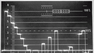
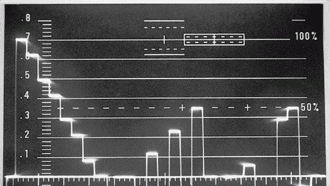
Figure 1. This sequential display shows a 100/0/100/0 color bars signal in the E’Y, E’B-Y, E’R-Y format.
Waveform monitors capable of carrying out such tests are readily available but are engineering and maintenance tools rather than operators' signal monitoring tools. Such tests are therefore carried out when accepting equipment or a complete system.
Monitoring the bit-serial digital signal beyond the originating point, at the input of the receiver (digital DA, production switcher, etc.) following a long coaxial cable, is misleading. The digital signal may be buried in noise but, if properly equalized and reclocked, will provide an excellent reconstruction of the original signal. It would be beneficial to be able to measure the bit-error rate at every input using the EDH concept. An ideal situation for large installations would be to incorporate EDH processors at every routing switcher input and output. This would allow the integrity of all input and output signals to be checked, and the results reported to a central diagnostic computer. But EDH is not universally implemented.
Monitoring video information
Get the TV Tech Newsletter
The professional video industry's #1 source for news, trends and product and tech information. Sign up below.
In a component digital environment, if the original component analog signal meets the relevant quality requirements, it will not be degraded after converting to a digital representation. This leads to the concept of source accountability, which means that the signal-generating equipment (e.g. CCU, CG, VTR and production switcher) operators need to verify that the analog information carried by the bit-serial “carrier” meets the requirements. The requirements fall under two distinct categories:
Figure 2. In a diamond display of a legal 100/0/100/0 color bars signal, the vectors are contained within two diamond-shaped electronic graticule patterns.
Legal signals: A set of component analog video signals is considered legal if each component signal is contained within the specified range of the format (e.g. 0mV to 700mV for E'Y, E'G, E'B and E'R or ±350mV for E'B-Y and E'R-Y). Even if the signal is within the specified voltage range of one format, it can exceed the limits when translated to another format. Component signal distribution channel gain errors will result in illegal signals.
Valid signals: A video signal is considered valid if it remains legal when translated into any other format. If properly generated, processed and distributed to compatible equipment, these signals reach but do not exceed the set limits. A valid signal is always legal, but a legal signal is not necessarily valid.
For example, a legal set of E'G, E'B and E'R signals can be encoded into an NTSC 100/7.5/100/7.5 color bars signal. This signal is perfectly legal but creates problems with NTSC analog transmitters. This is due to a major flaw of the NTSC system. When the NTSC color standard was developed in 1952-53, the transmission concept of analog terrestrial transmission was already well-entrenched. The basic characteristics were negative modulation with sync (-40 IRE) at 100 percent of carrier modulation, blanking (0 IRE) at 75 percent of carrier modulation, and white (100 IRE) at 12.5 percent of carrier modulation. This allowed for 12.5 percent headroom before carrier cancellation (at 120 IRE video signal amplitude), which was perfectly acceptable. Color television consisted of the addition of chrominance information transmitted as sidebands of two suppressed color subcarriers in quadrature phase.
Figure 3. The vectors of an illegal signal exceed the boundaries of the diamonds on a diamond display.
Even with reduced (by scaling) color difference signal amplitudes, a 100/7.5/100/7.5 color bars signal would result in a 131 IRE video signal amplitude for full-amplitude yellow and cyan bars, and video carrier cancellation accompanied by intercarrier buzz. The fathers of NTSC color television determined high-intensity yellow and cyan colors are not encountered in real life, so video carrier cancellation is unlikely to occur unless the camera is misadjusted. To avoid video carrier cancellations, the color bars signal to be used with video transmitters is 100/7.5/75/7.5. So 100/7.5/100/7.5 color bars are illegal.
Illegal signals were relatively rare until the appearance of digital character generators that could generate synthetic full-amplitude yellow and cyan colors, leading to transmitter overload and audio intercarrier buzz. Contemporary illegal signal problems occur when component digital signals (Y, CB, CR) are converted into G, B, R or analog composite NTSC or PAL. When operating in a composite analog environment, the use of NTSC or PAL waveform monitors can warn the operator that an illegal signal was generated. In a digital component environment, this is not possible unless the signal is converted into NTSC or PAL and an analog waveform monitor is available, which may not be the case.
Proprietary monitoring solutions
Tektronix has developed a family of component digital waveform monitors (WFM 601) that tell the user if the signal is legal or illegal. Two specific displays are available. The diamond display is a component vector display designed for the GBR format. Valid GBR signals generate vectors that are contained within the two diamond-shaped electronic graticule patterns. B-G errors affect the top diamond display and R-G errors affect the bottom diamond display. Figure 1 shows a sequential display of a legal 100/0/100/0 E'Y, E'B-Y, E'R-Y analog component color bars signal. This signal is legal when converted to E'G, E'B, E'R format, and the vectors in Figure 2 are contained inside the two diamond boundaries. Figure 3 shows a situation when the signals are not legal and the vectors exceed the diamond boundaries.
Figure 4. The signal in this arrowhead display has an excessive yellow chrominance level reaching 131 IRE.
The arrowhead display plots the luminance on the vertical axis and the chrominance on the horizontal axis. In Figure 4 there are three sloping lines. The outer line delimits 131 IRE, the one to its left delimits 120 IRE and the innermost line delimits 100 IRE. In this display we have a vector touching the 131 IRE line, generated by yellow letters from a character generator, and a vector barely missing the 100 IRE line, generated by blue letters. This display indicates transmitter overload and intercarrier buzz due to the illegal signal coming from the character generator.
Michael Robin, a fellow of the SMPTE and former engineer with the Canadian Broadcasting Corp.'s engineering headquarters, is an independent broadcast consultant located in Montreal, Canada. He is co-author of Digital Television Fundamentals, published by McGraw-Hill.
Send questions and comments to:michael_robin@primediabusiness.com
