Monitoring incidental phase modulation (ICPM)

In the late 1970s, television de- modulators became available with synchronous detectors, providing a method of monitoring the in-phase and quadrature signal components of television transmitters. Standards for ICPM were developed that helped improve audio quality and reduce video nonlinear distortion. While there has recently been an emphasis on digital television transmissions, there remains a need to maintain the quality of broadcast analog signals in the interim. This article discusses the effects of ICPM and methods of monitoring it with the new generation of equipment currently available.
In television broadcasting, the picture is carried by amplitude modulation (AM) of an RF wave while the audio is carried by frequency modulation (FM). Theoretically, in AM the signal varies the amplitude of a carrier wave, generating sidebands, but does not affect the carrier frequency. In practice, anomalies in the modulation process can cause the carrier frequency to vary slightly with the video signal level. The resulting time-varying frequency, and thus varying phase of the vision carrier, is known as incidental phase modulation, ICPM.
There are two basic types of circuits for demodulating amplitude-modulated signals: envelope and synchronous detectors. Envelope detectors are not sensitive to ICPM, but synchronous detectors are. Synchronous detectors provide better high-frequency response and thus display resolution, while envelope detectors lose resolution due to vestigial sidebands because of an effect known as quadrature distortion. The net effect of all of this can most easily be seen in differential phase measurements. ICPM can translate almost directly to differential phase errors when measured through a synchronous detector, while an envelope detector will respond primarily to the actual differential phase. Originally, television receivers used envelope detectors because of the simplicity of the circuitry required compared to synchronous detectors, so ICPM-induced differential phase was not a major issue. Large-scale integrated circuits have allowed manufacturers to employ synchronous and quasi-synchronous detectors that translate ICPM into differential phase distortion, thus degrading the color fidelity of the picture in some conditions.
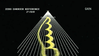
Figure 1. Pictured is a full-field stair-step test signal with an ICPM display resolution of 2° per division. The frequency response of this particular demodulator is limited to 800kHz in the I and Q channels.
In television broadcasting, audio is carried by frequency modulation (FM) on a carrier offset in frequency from the AM picture carrier. Television receivers typically combine the picture carrier and the audio FM signal to create an intermediate frequency signal for audio detection. Combining the two signals causes any time-varying phase in the picture carrier, or ICPM, to generate picture-related noise in the output of the audio detector. Thus, ICPM can cause video-related sound buzz and poor stereo separation.
ICPM monitoring
A television demodulator with two synchronous detector outputs, one in phase (I) and the other detector (Q), operating in quadrature to the picture, RF carrier and a display device, are required for ICPM measurements. The I channel is essentially the normal video signal; the Q channel output is proportional to the ICPM error. (See Figure 1.) Typically, ICPM is displayed in a polar graph expanded around quadrants three and four.
Get the TV Tech Newsletter
The professional video industry's #1 source for news, trends and product and tech information. Sign up below.
Mathematically, ICPM is equal to the arctangent of the quadrature component divided by the in-phase component of an AM signal: ICPM = ARCTAN (Q/I). In practice typical ICPM values range from less than one degree to ±45°. While the FCC does not have a specified limit for ICPM, there is a recommendation that it be limited to ±3°. ICPM in tens of degrees normally would be unacceptable, but can be encountered during initial setup.
Early waveform monitors, which had auxiliary horizontal inputs, were used with external graticules for ICPM measurements. Specialized waveform monitors followed with features such as internal ICPM graticules. These units have been largely phased out since then by manufacturers.
Normally, a five-step staircase signal is used for ICPM testing. This provides discrete RF carrier levels, from sync tip to white, for ICPM measurements. Using a full-field unmodulated staircase signal provides the highest resolution measurements. An NTC7 VIT, or FCC Composite VIT signal, can be used, but the resolution will be reduced by effects of the subcarrier modulation and the low duty cycle. (See Figure 2.)
Figure 2. The ICPM display for an off-air NTC7 VIT signal is shown. The variable persistence of the rasterizer allows ICPM to be observed in relatively high noise levels during normal programming.
The need to monitor and maintain high-quality analog broadcasts today is no less than in the past, but now it can be met cost-effectively with the right solutions. One need only look to products that are based on proprietary 10-bit rasterizing technology. Such solutions are capable of delivering sharp, analog CRT-like displays in conjunction with microprocessor processing that provides on-screen waveforms, adaptive graticules and numerical read-outs of important parameters.
A television demodulator, such as the Tektronix 1450, Rhode & Schwarz EFA.93 or Modulation Sciences 320, is required to demodulate the RF signal to baseband video, and to provide the in-phase and quadrature signal. The I and Q signal, and the baseband signal are then connected to the input of systems such as the Magni AVM-510A-T automated video monitor, which has specialized transmitter-testing capability, and provides an on-screen display that can be viewed on a color picture monitor.
Chuck Barrows is vice president of sales and marketing for Magni Systems.
