Revisiting Shannon
The year was 1948, 20 years after Harry Nyquist wrote his article “Certain Topics in Telegraph Transmission Theory,” in which the Nyquist sampling principles were first presented. During this period (1928 to 1948) broadcast engineers built a countrywide network of analog audio AM transmitters, developed the concept of analog audio FM transmission and, in 1941, came out with the first high-definition television standard (NTSC 525/60).
By 1948, the FCC had finally (or so it seemed) frozen FM (88MHz to 108MHz) and TV (channels 2 to 13) channel allocations, allowing for an energetic and speedy development of FM and TV broadcasting. Bell Laboratories was preoccupied, as usual, with the efficient (bandwidth-saving) transmission of low-noise telephone conversations. All these analog systems suffered from the less than ideal performance of the transmission link between the signal source (microphone or TV camera) and reproducer (loudspeaker or CRT). Analog signal distribution link impairments were studied at long length and fall in three distinct categories:
- Linear distortions (frequency and group delay response)
- Nonlinear distortions (harmonic and intermodulation distortions)
- Noise (random and coherent)

Figure 1. A typical digital video communication system. Click here to see an enlarged diagram.

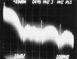
Figure 2. Spectrum of 270Mb/s 4:2:2 component digital bit-serial signal. Click here to see an enlarged diagram.

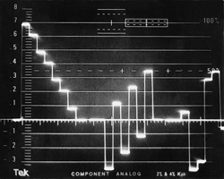
Figure 3. Sequential display of Y, PB, PR 100-percent color bars signals. Click here to see an enlarged diagram.

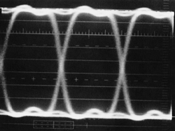
Figure 4. Eye-diagram of the SDI signal at the output of the channel encoder. Click here to see an enlarged diagram.

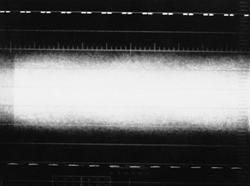
Figure 5. SDI signal after passing through a 200-meter coaxial cable. Click here to see an enlarged diagram.
The professional video industry's #1 source for news, trends and product and tech information. Sign up below.

Figure 6. SDI signal output of 200-meter cable after equalization. Click here to see an enlarged diagram.
In an analog world, all these unavoidable and cumulative impairments of the electrical signal (audio or video) shape have a direct effect on the quality (or lack thereof) of the reproduced sound and picture. In a digital world, the cumulative electrical signal impairments have no effect on the reproduced sound or picture up to a point (the cliff effect) when the system suddenly fails.
It is at this moment in time, July 1948, that the Bell System Technical Journal published Claude Shannon's article “A Mathematical Theory of Communications.” A conclusion of this article appeared in October 1948. This article created the concept of information theory, with its main application in communication engineering.
Shannon's communication system
A communication system consists of several parts:
- An information sourceIt produces a message to be communicated to the receiving terminal.
- A transmitterIt operates on the message in some way to produce a signal suitable for transmission over the channel.
- The channelThe medium used to transmit the signal from transmitter to receiver.
- The receiverPerforms the inverse operation of that done by the transmitter.
- The destinationThe person or the equipment for whom the message is intended.
Figure 1 on page 26 shows the block diagram of a typical digital video communication system as found in contemporary digital video studios. The source encoder is the conventional set of three (Y, B-Y, R-Y) A/D converters followed by a time division data multiplexer. The output of the multiplexer is a sequence of CB, Y, CR parallel 10-bit words. The channel encoder transforms the bit-parallel digital signal into a bit-serial digital signal suitable for transmission via the chosen medium (coaxial cable). The signal is corrupted by thermal noise, which in a studio environment is contributed by the receiver input stage. The receiver channel decoder deserializes the received bit-serial signal and recovers the bit-parallel digital video signal. Poor signal-to-thermal-noise ratio at the receiver input may affect the capability of reconstructing the original signal, resulting in bits in error or missing altogether. The output of the receiver channel decoder is the original sequence of CB, Y, CR. The signal decoder is the conventional demul-tiplexer, followed by a set of three (Y, B-Y, R-Y) D/A converters recovering the original analog component video signals.
The bit-serial data rate is given by:
Bit-serial rate (Mb/s) = parallel word rate (Mwords/s) × number of bits per word
The SDTV 4:2:2 bit-serial rate is equal to:
Bit-serial rate = 27 Mwords/s × 10 bits/word = 270Mb/s
The normalized HDTV bit-serial rate based on 60 fields/s is equal to:
Bit-serial rate = 148.5 Mwords/s × 10 bits/word = 1.485Gb/s
The 59.94 fields/s data rate is equal to 1.485Gb/s/1.001.
Shannon's communication channel capacity
According to Shannon, a noisy communication channel has a specific capacity measured in bits per second. The channel capacity is given by the formula:
C(b/s) = B log2 [1+(S/N)]
Where:
B = the channel bandwidth (Hz)
S = the received signal power (W)
N = the accompanying noise power (W)
Shannon's theorem states that it is theoretically possible to transmit information with a low probability of error through a channel having a specific capacity, provided that the transmission rate is lower than the channel capacity. Shannon does not specify the means of obtaining an error-free transmission over a specific transmission channel but simply states that there are means of achieving it.
Each method results in a specific channel coding. The channel coding describes the manner in which the 1s and the 0s of the datastream are represented on the transmission path. There are many channel coding standards, and they all aim at optimizing some aspect of the bit-serial digital signal, such as the spectrum distribution, the DC content and the clock recovery method. The SDTV and HDTV bit-serial channel coding uses the Non Return to Zero Invert (NRZI) scrambled method. The result is an increase in the number of 0 to 1 transitions and the randomization of their occurrence to aid in the recovery of the clock in the receiver. A detailed description of this method is beyond the scope of this article.
Practical applications in a studio environment
Figure 2 shows the spectrum of the 4:2:2 SDTV NRZI scrambled bit-serial digital signals with markers at 270MHz, 540MHz and 810MHz. The bulk of the energy is below 135MHz. The spectrum is typical of a suppressed-carrier pulse amplitude modulation (PAM) with nulls at the sampling frequency and its multiples. The distribution of this type of signal requires wide bandwidths on the order of half the clock frequency, in this case 135MHz. This requirement can be easily accommodated in a studio environment given adequate hardware technology. Figure 3 on page 26 shows the sequential display of the Y, Pb, Pr signals for a 100 percent color bars signal, the “message.” Figure 4 on page 26 shows the eye diagram of the SDI signal at the output of the channel encoder. Figure 5 shows the same signal at the output of a 200-meter coaxial cable. Note that the signal is buried in noise. Figure 6 shows the signal of Figure 5 passed through an equalizing network with a peak at 135MHz. Note that the 0s and the 1s are clearly identifiable, and the decoded signal would look like Figure 3.
The distribution of the bit-serial digital video signals over landlines, on-air transmitters or by satellite requires a reduction of the bit rate to match the existing standard communication channel capacity.
Michael Robin, a fellow of the SMPTE and former engineer with the Canadian Broadcasting Corp.'s engineering headquarters, is an independent broadcast consultant located in Montreal, Canada. He is co-author of Digital Television Fundamentals, published by McGraw-Hill, and recently translated in to Chinese and Japanese.
Send questions and comments to:michael_robin@primediabusiness.com
