Creating, transporting a stream

While this tutorial is about digital video testing, don’t, as they say, give up your day job or sell your waveform monitors and vectorscopes on eBay. In this case, your day job is to closely monitor the analog baseband input of digital video and audio ingest systems to verify that all levels are optimal. You, Ms. or Mr. ingest engineer, are the final arbiter of the picture and sound quality as it enters the digital domain, and you need good tools to do your best. Baseband video comes with knobs: Don’t hesitate to use them judiciously.
A quality digital video signal begins as one with all technical values of the analog baseband input signal closely scrutinized, verified and adjusted to conform to industry and facility standards as it is digitally ingested. Baseband video parameters include noise, artifacts, amplitude, hue, chroma, frequency response, frequency-dependent phase errors (group delay), differential gain and differential phase. Once ingested, these significant visual and aural details are virtually cast in cement.
The quality of an analog signal starts in the analog physical world, in that it vibrates the diaphragm of a microphone or passes through a camera’s prism. It will never be better than it is at the point of digitization. Inherent to analog recording, playback and distribution technology, even the best analog systems incrementally degrade the quality of the signal as it travels along the chain of circuits, wires, equipment and electromagnetic waves. Properly maintained digital systems preserve the quality of that digitized analog input signal through chains of signal processing, storage, transport and distribution, regardless of complexity or distance. At the end of the chain, the digital representation of the original analog input emerges virtually untouched and is reintroduced to the analog physical world through video displays, loudspeakers and headphones.
Unlike analog signals, which degrade at a somewhat linear rate until the quality is no longer acceptable, digital signals transition from virtually perfect to gone in short order. This effect is known as the digital cliff or cliff effect. There are some visual clues that may indicate that your video signal is close to the digital cliff, such as macro blocks or white dots. The next step from that point is a lost signal. The goal of broadcast engineers and technicians is to monitor and maintain the quality of service (QoS) of digital systems to prevent failures that could push the system over a digital cliff and affect the quality of experience (QoE) at the viewer’s location.
QoS and QoE are closely related, in some ways proportionately and in others inversely. For example, one method an IT-oriented technician might use to improve QoS is to reduce bandwidth by increasing compression, assuring fewer errors. On the other hand, this type of QoS improvement can reduce the QoE because the viewer may notice lower video quality as a result of higher compression. Determining and achieving the optimum balance is often a decision made by broadcast engineers and managers during which both factors must be seriously evaluated.
Serial digital video and audio data, including metadata, auxiliary and ancillary data, is usually called the transport stream and is carried on the physical layer, also known as the transport layer. At its root level, the transport layer can simply be the coaxial or fiber-optic cable that carries the transport stream from origin to destination. At the opposite end of the spectrum, transport layers can include IP or TCP/IP across a LAN, WAN or the Internet or the RF signal from a DTV transmitter or WiFi system. Transport layers have analog or pseudoanalog characteristics, meaning they become more susceptible to errors at higher data rates and longer cable runs, just as high frequencies roll off analog signals proportionate to the length of the cable. Typically, the higher the bit rate and/or the longer the cable, the more stress it puts on the transport layer or layers.
To verify the quality of a transport layer, it is usually “stress tested.” Stress tests are typically an out-of-service test that can be either experimental or scientific. At its most simple experimental level, a stress test can consist of transmitting a 270Mb/s SD-SDI or 1.485Gb/s HD-SDI signal via coaxial cable or fiber to its destination and adding lengths to the coaxial cable or fiber until the cliff effect occurs at the destination. The minimum physically necessary transport layer cable length, divided by the total length of the experimental transport layer cable at the point failure is detected, subtracted from 1.0, is a measure of transport layer headroom percentage. Opinions on minimum headroom vary, but in this case, more is always better.
The professional video industry's #1 source for news, trends and product and tech information. Sign up below.
Clearly, there are more scientific methods to make stress test measurements, such as using sophisticated test gear to explore and precisely measure such parameters as rise times and signal-to-noise ratios. But at the end of the day, whether you use the experimental or scientific approach, the idea is to confirm that you’re not building your digital foundation too close to the cliff.
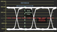
Another universal, and often more scientific, test of streams and layers is the eye pattern test. The eye pattern test is a visual representation of the analog signal transporting the digital data as observed on an oscilloscope. Depending on the sophistication and design of the oscilloscope, the test can identify and measure important details such as signal amplitude, rise times, overshoot and, in some cases, specific jitter issues as defined by SMPTE259M (SD-SDI), SMPTE292 (HD-SDI) and RP184 (SMPTE jitter specifications). With a general-purpose oscilloscope, it is still possible to observe the eye pattern, and even a basic uncalibrated view can often be quite revealing. To view an eye pattern on a general-purpose oscilloscope, connect the digital data stream to the vertical input and use the data rate to trigger the horizontal sweep.
The fundamental concept of eye pattern diagrams is that the clearer and more well-defined the eyes and crossover points appear on the oscilloscope, the healthier the system. Transport stream eye pattern measurements should be taken as close to the source as possible to reduce or eliminate issues introduced by transport layers, or you may want to test only the transport layer with a separate eye pattern test starting with a verified good source. Any technical issue that causes the eye to close can reduce the robustness of the received signal and push the system closer to the digital cliff.
As is the rule in broadcast engineering, the more sophisticated the test equipment, the more accurate the measurements. Several manufacturers offer a variety of dedicated oscilloscopes, raster devices and signal generators that can enable engineers to identify large and small problems in transport layers and data streams. As always, the need for such equipment is usually dictated by the urgency of the issue and your budget.
