Doherty Amplifiers Push Efficiency

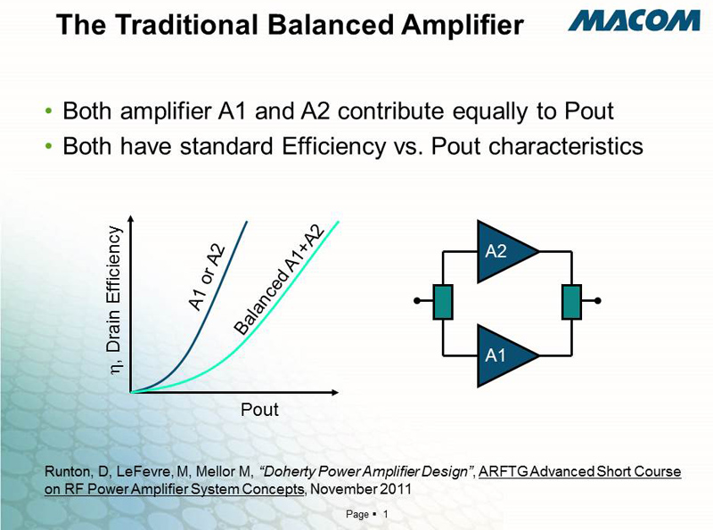
Figure 1
ALEXANDRIA, Va.—William H. Doherty was an engineer with Bell Telephone Laboratories in 1936 when he invented a circuit that used two tubes running in Class B configuration to act as a linear amplifier for radio transmitters. An earlier design that used Class B tubes was the push-pull configuration, which usually needed a transformer to combine the output of the two tubes (Figure 1). Push-pull was efficient and powerful, but it was not the end of the game for efficiency.
The Doherty amplifier didn’t need a transformer and boasted an efficiency advance over push-pull circuits. Although there have been many developments in amplifiers over the decades, some DNA from Doherty’s design is now making its way into modern television transmitters.
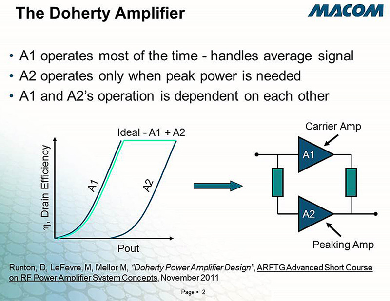
A typical Doherty amplifier configuration using tubes has them in common cathode mode, with one tube amplifying the bulk of the RF carrier (Class B or Class AB mode) and the other tube handling the peaks (Class C mode). The outputs of the two tubes are combined in a reactive network (Figure 2).
There were many refinements starting almost immediately, but Doherty amplifiers gave only a marginal efficiency boost in the era of analog radio and television broadcasting. The technology mostly was forgotten until the digital cell phone era began in the middle of the last decade, when it was discovered that Doherty designs gave an efficiency boost to virtually every form of digital cellular signal. The key is the higher peak-to-average ratio that digital transmission has in comparison to analog transmission.

Figure 2
With digital broadcasting and its higher peak-to-average ratios, Doherty amplification can result in up to a 14-percent efficiency improvement over more traditional amplification when driven by digital signals. That’s a serious improvement that was widely incorporated throughout the cellular industry.
Get the TV Tech Newsletter
The professional video industry's #1 source for news, trends and product and tech information. Sign up below.
HOW IT WORKS
One of the refinements to Doherty’s original circuit was to use one tube configured for Class AB operation and another for Class C. In both this and its classic design (two Class B amplifiers), a Doherty amplifier splits the input signal using a power divider and sends signal equally to each amplifier with a 90-degree phase difference.
On the input, the signal is split using a 3 dB quadrature coupler, such as a Lange or branchline hybrid (branchline is shown in our schematic). This is pretty much the same as the input to any balanced amplification scheme.
The output of the Doherty configuration is more complicated. Since the two signals are out of phase by 90 degrees, the addition of a quarter-wave transmission line on the output of the peaking amplifier will bring the two back into phase. They can then be combined using an R/C network.
The output of the combined amplifiers segments has the two in parallel, creating a Zout/2 impedance. This can be stepped up to Zout using a quarter-wave transformer. In a 50-Ohm system, the transformer needs to be 35.35 Ohms.
At lower-power operation, only the Class AB carrier amplifier functions and the Class C amplifier is dormant. Operating at these lower power levels, the Class AB carrier amplifier sees a modulated load impedance that results in higher efficiency and gain.
When the signal peaks, both amplifiers operate and both see load impedances that enable maximum power output. For digital modulation schemes that cause the exciter to spend much of its time at its modulation peak, the result is greater efficiency. At the power output of most digital television transmitters, that efficiency shows up immediately in lower operating costs.
Note that you get the efficiency advantage with a Doherty amplifier only at overall power levels that are backed off the maximum. Pushing a Doherty amplifier to maximum power eliminates the efficiency gain.
CHALLENGES
Although the inherent efficiency of the Doherty design makes a lot of sense in digital transmitters, an effective design presents some challenges. For one, a Doherty design is slightly less linear than a dual Class AB amplifier, which can result in higher distortion.
However, pre-correction and feed-forward linearization used in many transmitters can eliminate most of the linearity distortions, and good amplifier design can deal with the rest. And the really good news is that Doherty amplifier configurations work in solid-state designs as well as tubes.
Today, television transmitter manufacturers are building models with Doherty amplifiers, including Comark and Rohde & Schwarz. These are solid-state transmitters that can supply output power as high as 100 kW, with efficiencies that rival the best MSDC IOT transmitters.
For example, the Comark Parallax uses broadband 50-Volt LDMOS transistors in a Doherty configuration to provide up to 25 kW in a single rack cabinet. Adding cabinets can boost the Parallax’s power to 100 kW.

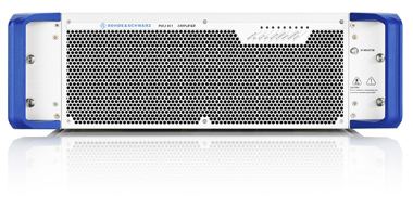
Rohde & Schwarz PMU901 Doherty amplifier module
Rohde & Schwarz has transmitter models for both UHF and VHF TV that use Doherty amplifiers, and also has Doherty technology in digital audio broadcasting products. The company’s THU9 UHF TV transmitter can deliver up to 50 kW using 48 amplifier modules.
Since the dawn of broadcasting, continuous advances in efficiency have meant that the next generation of transmitters is always the most efficient. Couple that with the intrinsic reliability and stability of transistors as compared to tubes (such as IOTs), and the latest generation of digital TV transmitters is advancing the cause of both efficiency and reliability.
Of course, solid-state amplifiers achieve high power output by using many low-powered modules added together. This adds complexity and signal loss, as all those power modules are combined and cooled. On the other hand, most manufacturers let you pull out a single bad module—even liquid-cooled modules—as the transmitter hums along using the remaining modules.
Doherty amplifier technology has allowed solid-state television transmitters to reach one of the Holy Grails of TV broadcasting: a solid-state transmitter with efficiency similar to tube transmitters.
What will the next generation bring?
Bob Kovacs is the former Technology Editor for TV Tech and editor of Government Video. He is a long-time video engineer and writer, who now works as a video producer for a government agency. In 2020, Kovacs won several awards as the editor and co-producer of the short film "Rendezvous."

