Fiber Options for 4K

40 and 100 Gigabit fiber-optic Ethernet standards
ORANGE, CONN.—With the rapid growth of Ethernet connectivity and applications within modern broadcast and studio facilities, it is inevitable that networks will need connection speeds beyond 10 Gbps. Fortunately, standards now exist for both 40 and 100 Gbps interfaces in IEEE 802.3ba-2010. Several manufacturers of high-performance Ethernet switches and IP routers have introduced products that support both interface speeds, and many are working on second- and third-generation products.
COPPER OR FIBER?
Implementers of high-speed Ethernet interfaces have several technologies to choose from (in order by increasing performance and cost): copper cable, multimode fiber and single-mode fiber. Signals flow in parallel “lanes” across an interface, similar to a superhighway with multiple traffic lanes. Each lane runs at a specified bitrate, and the data bytes are separated into each lane using round-robin allocation for each 64-bit data word (these are padded up 66 bits each using 64b/66b encoding).
Copper links for 40G and 100G are extremely limited in distance (7 meters is the spec). These connections use multiple parallel signals, with a pair of balanced-impedance conductors for each lane of data traffic. For 40G, as specified in 40GBASECR4, four shielded copper pairs are used in each direction, for a total of eight twinaxial signal paths. For 100G, as specified in 100GBASE-CR10, ten shielded copper pairs are used in each direction, for a total of twenty signal paths.
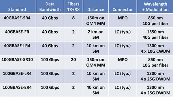
Multimode optical connections use a single fiber for each data lane. For 40G, eight fibers are used, and for 100G, 20 fibers are used. Each fiber has a 50 micron core inside a 125 micron cladding, and transports a single 850nm optical signal. Distances depend on the type of fiber used, with OM3 fiber supporting 100 meters and OM4 fiber supporting 150 meters. The 40GBASE-SR4 interface uses eight fibers in an MPO (multifiber push-on, standardized in IEC 61754-7) connector that has a total of twelve fibers installed. (Cisco has introduced a proprietary version offering 400 meters of transmission called 40GBASE-CSR4). The 100GBASE-SR10 interface uses twenty fibers in an MPO connector that has a total of twenty-four fibers.
Single-mode optical connections offer a wider variety of interfaces, with distances measured in kilometers. Many of these interfaces use multiple wavelengths (“colors”) of light on a single fiber, using a technology called wavelength division multiplexing. Two types of WDM can be used: Coarse WDM, where the wavelengths are held to relatively loose tolerances and are widely spaced across the frequency spectrum, and Dense WDM, where the wavelengths are more tightly controlled and can be much more closely spaced.
For 40G signals, 802.3ba defines the 40GBASE-LR4 format, using 4 CWDM wavelengths to transmit four lanes of 10.3125 gigabaud (to support 64b/66b encoding) over one single mode fiber. Two fibers, typically with LC connectors on each end, are used to form a bidirectional link of up to 10 km. In 2011, the IEEE added a new 40G signal in 802.3bg called 40GBASE-FR that transmits data using a single-wavelength lane operating at 41.25 gigabaud, which operates over distances up to 2 km.
Get the TV Tech Newsletter
The professional video industry's #1 source for news, trends and product and tech information. Sign up below.
For 100G signals, two interfaces are currently standardized, both of which use four 25.78125 gigabaud data lanes in each direction. A long-haul link that uses single mode fiber of up to 10 km is called 100GBASE-LR4. An extended range link that can support up to 40 km of single mode fiber (with controlled fiber and connector losses) is called 100GBASE-ER4. Both interfaces use one DWDM wavelength for each data lane, and operate over a send and receive pair of fibers that typically use LC connectors.
IMPLICATIONS FOR BROADCASTERS
Current 100G interfaces are extremely expensive (over $100,000 per end) and are implemented primarily in data-center focused “big iron,” where dozens or hundreds of 10G ports are combined into a chassis and then 100G links are used to connect between chassis. These systems typically occupy multiple rack units and consume kilowatts of power, at least as implemented using today’s technologies. Most systems on the market today use a “pay as you populate” model, where expensive optical modules are sold separately (QSFP+ modules for 40G, and CFP modules for 100G) from the interface modules. This helps control costs somewhat, although the circuits needed to feed the optical modules are also quite expensive. 40G interfaces are more common and more affordable, with multiple vendors providing low-profile equipment (1 RU) and smaller numbers of 1Gbps and 10 Gbps ports per system.
In theory, a single 100G link can support up to 66 HD-SDI signals operating at 1.5 Gbps. Many forecasters predict that the cost of both 40G and 100G connections will drop significantly over the next 3–5 years, primarily driven by the needs of “big data” across many industries. Studios and broadcasters, particularly those working with 4K video, will certainly be able to take advantage of these new products as they come onto the market.
Wes Simpson is President of Telecom Product Consulting, an independent consulting firm that focuses on video and telecommunications products. He has 30 years experience in the design, development and marketing of products for telecommunication applications. He is a frequent speaker at industry events such as IBC, NAB and VidTrans and is author of the book Video Over IP and a frequent contributor to TV Tech. Wes is a founding member of the Video Services Forum.

