The evolution of the pluggable module
The video broadcast market is a niche market with multiple complexities and particularities. Two common examples are pathological data encoding schemes and 75V coaxial cable. The following article relates the evolution of pluggable modules in telecommunication and their migration into the broadcast market. The article will cover the various types of modules, the pros and cons of these components, and the introduction of new pluggable technologies in the broadcast space: the video SFP and the emSFP.
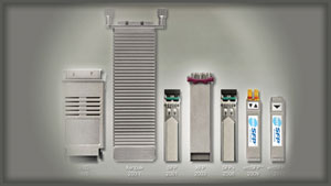
Figure 1. Evolution of the size of the pluggable
Pluggables in the telecommunication market
The main reason behind the pluggable is simple. Historically, systems designers had to choose between fixed copper ports or fixed optical ports for physical I/O applications. Each designer struggled with the decision of how many copper and how many optical (single-mode or multimode) ports were needed to support LAN, WAN and the new SAN markets.
This might sound familiar for equipment designers, users and integrators as we are faced with these decisions more often than not. This dilemma was present in the 1990s for telecommunications systems until fiber physical connections became dominant. However, the challenge is still present for broadcasters today. Coaxial cable is still the dominant physical layer connection, but fiber and twisted pair streaming mediums are supported in almost every new system deployment.
Therefore the question arises: How can a designer/manufacturer/integrator create a uniform platform supporting multiple physical mediums?
Telecom OEMs responded to this request by creating the pluggable form factor, starting with the GBIC and migrating to the SFP, Xenpak, XGP, XPAK, X2, XFP, SFP+, etc. (See Figure 1.) With the convergence of telecom and media industries, particularly in the past five years, the expertise and experience of telecom has been quickly adopted in the broadcast sector with the SFP and now the emSFP.
Get the TV Tech Newsletter
The professional video industry's #1 source for news, trends and product and tech information. Sign up below.
RAS
Reliability, availability and serviceability (RAS) have been key factors for Fibre Channel transport. The strong penetration of 4.25Gb/s Fibre Channel disc interconnect puts enormous pressure on manufacturers to support both copper and fiber interfaces. The response of Compaq Computers, Sun Microsystems, Vixel Corporation and AMP was the gigabit interface converter (GBIC). (See Figure 2.) This interface gave the full flexibility of copper, multimode fiber and single-mode fiber without changing the hardware platform.
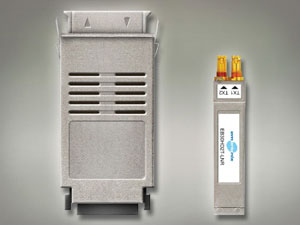
Figure 2. GBIC versus emSFP (right). Images courtesy of Embrionix.
The GBIC was accepted in 1999 and became a valuable option for new systems in Fibre Channel deployments. The extra flexibility sparked interest in the networking industry as well. The ’90s also showed the popularity and acceptance of the SC-style (subscriber or standard) connector, followed by the ST (straight tip) and FC (ferrule) connector. The newest connector style during this time was the LC (Lucent) connector measuring roughly half the size of the SC. Prior to the introduction of the SFP, some manufacturers created the small form factor (SFF) module, but it was not pluggable. (See Figure 3.) Unfortunately, the limitations of the SFF were quickly identified. Because the SFF had to be soldered on the board, it limited ease of use, interchangeability and in-field repair. The parameters of RAS were not met.
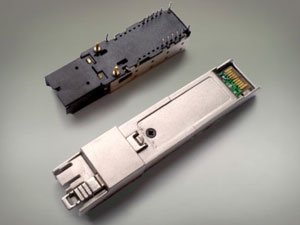
Figure 3. SFF (top) versus optical emSFP (bottom)
The SFP
The GBIC had some limitations in speed with a maximum 2.125Gb/s data rate. And it was large — approximately 1in x 2.5in. But industry acceptance pushed 14 manufacturers to create a new and improved pluggable. A new Multi-Source Agreement (MSA) was formed in 1999 to address the need for faster and higher density modules, and the SFP was born. The SFP supported faster rates up to 4.25Gb/s and a reduction in size (approximately half the size of the GBIC). Even so, the SFP and the GBIC both used 20-pin blind-mate connectors, allowing for a logical migration from GBIC to SFP.
During the time of introduction, the only type of pluggable configuration was the transceiver (1-IN/1-OUT), hence the MSA specified a transceiver pin assignment only. For the broadcast industry, requirements are slightly different. Video signal configurations follow unidirectional configuration and are rarely evenly distributed between inputs and outputs. For example, a core broadcast video router in a facility rarely has an equal number of input ports versus output ports. Naturally, a non-MSA standard was introduced allocating pinout assignments for dual-output and dual-input I/O configurations. The following table shows a comparison between the MSA and non-MSA pin assignments. (See Figure 4.)
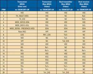
Figure 4. MSA and non-MSA pinout for SFP and emSFP
The SFP interface includes multimode and single-mode fiber via LC connector, copper interfaces such as HSSDC2 cable and 50V coax cable. The main function of the SFP was signal conversion from electrical to optical transmission. Additionally, it could be used to extend the reach of electrical signals over longer copper cables with careful cable driver design. Traditional video SFPs serve the same purpose.
The advanced emSFP is a more intelligent pluggable, offering a rich set of new features. For example, it can include features such as measuring eye diagrams and signal power level diagnostics. Or it can provide NTSC/PAL conversion to and from analog, or HDMI conversion to and from SMPTE SDI data streams. The advanced feature set and processing of these modules, combined with the modularity of the SFP form factor, provides the configurability and flexibility demanded by the broadcast and media industries in a single, comprehensive system.
The SFP continues to prove its success through its rapid adoption by numerous manufacturers and users in the broadcast industry. Even today, more than 100,000 SFPs/SFPs+ are sold per month. As mentioned earlier, the SFP bit rate was limited to 4.25Gb/s, but the demand and requirements for 10Gb/s have been known for some time, and solutions are beginning to emerge. To be widely adopted, multiple new standards, one of which is the Xenpak, have been, and are being, developed.
Past solutions
The market continued to ask for more than pluggable compatibility. The demand for higher speed, lower power and smaller packages was unabated. The parallels of these technology requirements are seen throughout the industry. For example, processor speeds are always increasing, with smaller die sizes and decreased overall power consumption. With growing network traffic requirements driven by cellular and wireless Internet access, providers needed to find a good pluggable system to address the quickly increasing need for more bandwidth.
One of the first attempts was the Xenpak, a 2in x 4.5in pluggable module capable of transmitting and receiving four pairs of 3.125Gb/s data transmission. Due to the 8b/10b encoding overhead, the usable bandwidth was only 2.5Gb/s. Still, with four pairs at 2.5Gb/s, 10Gb/s pipes were possible. The Xenpak did have one big advantage: It did not need a cage. The standard relied on a PCB cutout to align the module. (See Figure 5.)
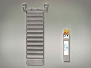
Figure 5. Xenpak versus emSFP (right)
But the Xenpak was too expensive, still too bulky and used too much power for the LAN/SAN environment. XGP, XPAK and X2 were created in an effort to meet the demanding new criteria. Similar to audio loudness control, every OEM vendor thinks their implementation, or specific algorithm, is the best for a number of reasons. In the end, users decide what is best for their facilities, and the need for a standard drives compromise. Standards, regulations and certain industry agreements are put in place to ensure a common system that enables widespread adoption of a technology and, therefore, a much larger market for all the vendors. By 2002, the industry was hoping the X2 and XPAK MSA would find a common ground and merge in a single system. Unfortunately, both were developed around the Xenpak and did not gain acceptance in the industry.
The successful XFP
By 2001, great progress in the optical component industry allowed the miniaturization of Receiver and Transmitter Optical Sub-Assemblies (ROSA and TOSA). (ROSA and TOSA will be discussed in a future article for Broadcast Engineering.) Today, these ROSA and TOSA are widely available at 10Gb/s speeds and higher. These components directly modulated or responded to light at 10Gb/s, thereby eliminating the need for the XAUI protocol carrying four pairs at 3.125Gb/s. The XFP MSA specification started in 2001, with 10 members. It outlined a small and efficient pluggable with specification 1.0 established in September 2002. (See Figure 6.)
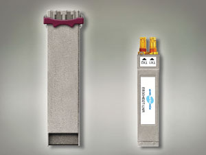
Figure 6. XFP form factor versus emSFP
Keeping pace with technology, smaller ROSA and TOSA optics were developed shortly after the XFP MSA specification. In 2008, the SFP was modified to handle more power and the higher 10Gb/s bit rate to become SFP+. Once again, the SFP form factor became the market leader. The new SFP+ supported 10Gb/s and up to 1.5W of power, requiring special cages with heat sinks to dissipate the thermal load.
The SFP+
The SFP+ is similar to the SFP. The main differences are the 10Gb/s optical transport speed and a slightly modified SFP housing for dissipating more heat. The mechanical differences increase power dissipation capacity to 1.5W and offer better signal integrity for the high-speed differential data. This data is carried over impedance-controlled traces run between the SFP+ module and the host system. A more robust connector was specified, and the new cage supports an optional top-mounted heat sink offering improved cooling for both convection and forced air applications. (See Figure 7.)
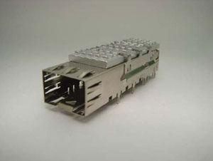
Figure 7. SFP+ cage with heatsink
Today, in addition to 1310nm and 1550nm wavelengths, the entire spectrum of CWDM and DWDM wavelengths are supported. This enables extremely high data rate transmission on a single fiber. High-power lasers at the transmitter combined with increased receiver sensitivity for PIN diodes enable long fiber links. Avalanche Photo Diodes (APDs) now fit inside the SFP+ cage, so they can be used as well. This increased power budget enables transmission distances of 100km, or more, without a repeater depending upon the unique aspects of a given system or fiber link.
The pluggable in the video broadcast/media market
As discussed earlier, the transceiver SFP was not popular in the broadcast and media industry for a number of commercial and technical reasons. Video transmission over fiber was expensive and only used for niche applications. But with HDTV, serial digital video speeds of 1.5Gb/s launched fiber into the mainstream of broadcast and media industries. Manufacturers first built their own electrical-to-optical (E2O) and optical-to-electrical (O2E) converters with discrete components. Hurdles such as pathological signal performance often impeded development. Careful design techniques were required to manage the high DC content of the SDI signal. Products that did offer error-free operation required entire circuit boards on components. They were bulky and expensive.
These early converters were inflexible and lacked real-time diagnostics. At this same time period, around the year 2000, rich, internal diagnostic features were not typically integrated with core equipment such as routers, multiviewers, cameras or production switchers.

Figure 8. emSFP products line 2012
Even though HDTV launched in 1998, it was not until 2004 that the first optical SFP (V_SFP) and SFF (V_SFF) for the video industry were developed that were capable of meeting the demanding requirements of the SMPTE SDI signals. In 2007, the broadcast industry looked to enable 1080p video signals pushing the data rate to 3Gb/s for SDI data transmission. And more companies started to provide SFPs that were capable of managing 3Gb/s data and the video pathological signals. In addition to transceivers, dual transmitters and dual receivers were developed to more closely meet the needs of the broadcast and media industries.
Today, many suppliers offer basic optical SFPs. When manufacturers select optical SFPs, various factors must be taken into account: optical launch power, receiver sensitivity, mechanical robustness, internal diagnostics, and, of course, price and lead time.
Basic digital diagnostics are defined in the SFP MSA specification. The diagnostic information is accessible via a serial, industry standard, I2C bus. The host system can then control basic SFP parameters such as transmitter enable and get information from the SFP such as internal temperature, voltage or receive signal strength.
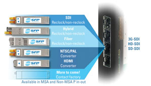
Figure 9. emSFP offering
The SFP brought various benefits to both manufacturers and users:
- Interoperability between equipment for fiber transmission;
- Simplified stocking and management of inventory;
- Small footprint for both products and inventory storage;
- Faster mean time to repair (MTTR);
- Faster time to market for product design.
The embedded SFP (emSFP)
The SFP is great for basic O2E and E2O for fiber, but copper cable is still widely deployed and must be supported, and standard SFPs do not help with system integration. If a facility or installation needs to handle multiple physical layers and different signal standards, you may need multiple converters. The emSFP was created to fill this need and to build one unique platform to support exactly what the user needs.
The emSFP product line covers the standard coaxial cable, fiber optic, CVBS (NTSC/PAL) to SDI conversion, HDMI-to-SDI conversion and ASI-to-IP encapsulation. These features enable a high level of integration in the core platform and a new level of flexibility for manufacturers and users.
In every case, these modules convert a serial SDI signal to the required physical layer format and transmission standard and protocol. These modules permit users to build a product today and future-proof the platform by upgrading the emSFP, not the core.
Internal I2C communication with the SFP allows easy integration with SNMP monitoring and control
software applications.
RAS for the broadcast and media industry
We have explored the history and timeline of pluggable modules, covering key components that shaped the telecom, broadcast and media industries. (See Figure 10.)
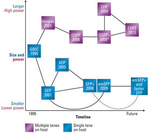
Figure 10. Pluggable timeline
SFP and SFP+ modules have proven to be the most accepted and widely used pluggable technology in telecom, and now broadcast. The constant demand for higher speed, more processing and flexibility, and lower power continues to shape the role of the SFP, emSFP and SFP+ in broadcast and media. The technical teething pains and RAS fundamentals that successfully shaped and contributed to the growth and success of networking worldwide are now available to the local broadcaster.
—Renaud Lavoie is president and CEO of Embrionix.
