A New Kind of FMI on The Horizon?

At the International Conference on Consumer Electronics earlier this month, I presented an invited paper on FMI to an audience of consumer electronics engineers.
FMI now has three aspects. The first is interference to reception of DTV signals on Channels 7–13, which is due to second-order distortion products generated within the receiving system.
That covers DTV receivers or downconverters and any signal amplifiers such as low noise pre-amplifiers or signal distribution amplifiers. FMI can affect DTV reception on Channels 4–13. There are different interference mechanisms for interference to DTV reception of low-band VHF channels from that for high-band VHF channels. Let’s start with the high VHF band.
One strong FM band signal
One strong FM band signal at 100.1 MHz would generate a second harmonic at 200.2 MHz, which falls within Channel 11. As Dr. Shannon said in his information theory, anything that is not the desired information is noise and DTV receivers take Dr. Shannon at his word. This FM signal translated to Channel 11 increases the noise in the desired channel.
Two strong FM band signals
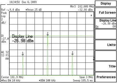
With two strong FM Band signals you also get one second-order intermodulation product whose frequency is the sum of the two FM band frequencies. If the second FM Band signal is 103.3 MHz, the IM2 = 204.4 MHz, which also falls in Channel 11. The power of this IM2 always is 6 dB greater than the power of each second harmonic assuming these harmonics are of equal power. This is shown in Fig. 1.

Fig. 1: Second harmonics of two FM band carriers at 181.0 MHz and 182.6 MHz each at –33 dBm and the second-order intermodulation product also produced by these FM band carriers is at 181.8 MHz (the average of the two secondharmonic frequencies) and is 6 dB stronger than those second harmonics. The other IM2 is the difference between the FM band carrier frequencies, 0.9 MHz to which I will return later.
Three or more FM band signals: F1, F2, F3…
In most medium-sized or large markets there are many more than two FM radio stations, some of which radiate up to 100 kW. These are spaced by at least 800 kHz so there can be up to 25 FM channel allotments in a community.
Given 10 strong signals, these form 45 pairs; 0.5* (102 –10). To give you a feel for this, consider the Portland, Ore. market with 22 FM stations from 88.3 to 107.5 MHz. These could form one half of [222 - 22] = 231 channel pairs. These will be spread out from 176.6 MHz to 231 MHz with the largest number (63) in Channel 10. Wow!
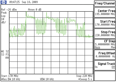
Of course, not all 22 operate at or near 100 kW. So the number of channel pairs, which generate significant second-order distortion products, is less. Fig. 2 shows how noise power spreads out over Channels 7–13.
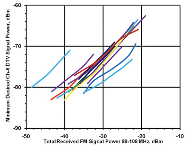
Laboratory test results of 15 NTIA-approved DTV downconverters tuned to Channel 6 were conducted by my colleague, Linley Gumm and the author. Those results are shown in Fig. 3.
In Fig. 3 the spread between the best and worst performing units approaches 20 dB.
This suggests that some of these products were designed by engineers who understood FMI, and by others who did not. For a given level of FMI, the plot shows the minimum usable DTV received signal power. FMI de-sensitizes these downconverters, and probably DTV receivers with the same tuners.
The spread in the maximum undesired (FM) signal power at a given desired DTV received power approaches 20 dB. This may be because some design engineers understood FMI while others working just from FCC rules, or from the ATSC guidelines document (A/74) and the NTIA minimum RF performance requirements for federally subsidized DTV downconverters were not aware of FMI.
One FM signal into a low VHF DTV channel
One strong FM band signal can only cause compression (also called desensitization of the receiver) of the desired DTV signal. Third harmonics of FM band signals fall outside of all TV bands so they can be ignored. Of far greater concern is interference from two or more FM band signals.
Two FM signals into a low VHF channel

Fig. 2: FMI spreads out across the entire high VHF band. With three FM Band signals there will be three second harmonics at 2F1, 2F2, and 2F3 and three second-order intermodulation products (IM2) of the form F1 + F2, F2 + F3, and F3 + F1, all of which fall in the high VHF band. This fact and their 6 dB greater power than second harmonics make them the determining factor behind FMI in the high VHF band. Of course, these will also cause compression of the desired DTV signal, but there will also be third-order intermodulation products. These are of the form:
2F1 – F2 where F2 > F1.
As F2 is 800 kHz or more above F1, no more than eight of these IM3 can fall within the 5.38 MHz IF bandwidth of DTV receivers. This is a real break for broadcasters.
Three or more FM signal into a low VHF channel
Well, here it comes. With three undesired signals, F1, F2 and F3, there will be multiple IM3 and here they are: 2F1 – F2, 2F2 – F3 and 2F1 – F3, which fall in some low VHF channels.
Let’s do the numbers: 2* 88.1 MHz – 107.9 MHz = 68.3 MHz. The lowest possible IM3 frequency from FMI is in Channel 4. Channels 5 and 6 are subject to FMI with even more IM3. Fig. 3 shows recent tests of NTIA-approved DTV downconverters receiving a DTV signal on Channel 6.
There is yet another kind of third-order distortion product, called triple beat. It is of the form: F1 + F2 – F3, F2 + F3 – F1 and F3 + F2 – F1. Let’s do the numbers: 88.1 MHz + 88.9 MHz (the two lowest possible FM carrier frequencies) – 107.9 MHz, (the highest possible FM frequency) gives us the lowest frequency for triple beats from FM signals into the low VHF band. This minimum frequency is 69.1 MHz, again in Channel 4, with more falling in channel 5 and the most in Channel 6.
Other forms, such as F2 + F3 – F1 fall above the FM band, but not in any TV channel. By experiment, I found that the power in each of these triple beats is 5 dB greater than that of the other third-order distortion products, IM3.
I calculated the number of triple beats generated by 4, 5 and 6 carrier frequencies; those numbers increase dramatically with the number of carriers. In the limit, 22 carriers (as we have in many medium to large markets) produce astronomical numbers.
Now we’ve found the real problem. It is not the IM3 that will be the dominant source of FMI. It is not that 5 dB difference in the power of a triple beat vs. an IM3, but the sheer numbers of possible triple beats.
Ask any CATV engineer. In 100+ channel systems, triple beats are the implacable enemy. Fortunately we only have 22+ FM carrier frequencies to worry about.
IS MORE FMI COMING?
No, I don’t mean more FM band carriers, nor higher-power FM carriers either. At the 2007 ICCE, we learned about a radical new DTV receiver topology.
In their continuing quest for lower-cost receivers, the way to do this is to more fully integrate the circuit functions onto a silicon chip, and to do it without off-chip components; that is to integrate everything onto an IC substrate.
This would be the ultimate in cost reduction, and incidentally, perhaps with large energy savings as well, something green to be advertised. But how do you integrate inductors with a satisfactory Q? So RF selectivity of such tuners may be a problem, spelled F-M-I.

Fig. 3: Test results of some NTIA-approved DTV downconverters. The minimum usable DTV received signal power is increased by the presence of strong FM signals from the 22 FM radio stations in Portland, Ore., as shown above. Note the large spread between units. As radio evolved, the IF frequency of radios went higher and higher and that was true for analog TV too. Now that trend is about to be reversed. The next generation of DTV receivers will include designs whose IF will be centered at or near 3.25 MHz.
This raises an interesting question. What about IF feed-thru? What is IF feed-thru? I first met this here in Portland, Ore., circa 1954. By then, TV receivers had an IF centered at 44 MHz. Downtown, there was a calling service transmitting 100 Watts on 43.58 MHz. That signal was picked up, not by our UHF-band antennas, but by the downlead and carried into the tuner where it found the mixer and passed through it, then through the IF amplifier and associated IF Filters, and on to the second detector where it beat against the visual carrier and produced a herringbone pattern we quickly learned to recognize as IF feed-thru.
Now, fast-forward to year 2010 when I expect low frequency IF DTV receivers to appear on the market. This time around, it won’t be one 100 Watt interferor; it maybe multiple 100 kW interferors (FMI).
There are no FCC rules that would apply to this situation. It is simply a matter of DTV receiver design rules having changed to more fully integrate everything onto a substrate.
The reason for writing this in a broadcast-oriented magazine is to alert broadcasters to a new kind of FMI, which I think is coming soon. As you have seen in this column, Channel 10 is the most vulnerable of the high VHF band channels to FMI, and Channel 6 is the most vulnerable in the low VHF band.
I do not expect FMI to be a problem to any UHF channel for receivers having a 44 MHz IF. But IF feed-thru would affect reception of weak DTV signals on all channels in receivers with a low frequency IF because the interference end-runs the tuner.
Now we will pick up the thread I mentioned at the front end of this column. You will remember that I showed that FM band signals generate IM2 two frequencies, F1 + F2, which always falls in Channels 7–13, and another F2 – F1 where F2 > F1. If F1 is the lowest FM carrier (88.1 MHz) and F2 is the highest FM carrier, then this IM2 is 107.9 MHz – 88.1 MHz = 19.8 MHz.
If the difference between F2 and F1 is 0.8 MHz, then the lowest IM2 frequency is 0.8 MHz. It can be shown that many of these F2–F1 components fall below 6 MHz into the low frequency IF band.
What will happen is anyone’s guess. Hopefully all low frequency IF receiver designers are already aware of these problems, but this could be wishful thinking. I’m an old timer and remember IF feed-thru quite well. This time, we won’t recognize it from a beat pattern on the screen; we may be confronted with blue screens and no sound, especially where the DTV signal is weak, and there are several strong FM signals. This is the message I hope I conveyed to my audience at ICCE.
Charles Rhodes is a consultant in the field of television broadcast technologies and planning. He can be reach via e-mail atcwr@bootit.com.
Get the TV Tech Newsletter
The professional video industry's #1 source for news, trends and product and tech information. Sign up below.
