ATSC Digital On-channel Repeaters at NAB Show

The amount of floor space devoted to transmitters at the 2010 NAB Show has dropped significantly over the last five years as the focus has moved from established high-power tube and solid-state amplifier technology to control systems, modulators and exciters. These don’t require as much room to show or demonstrate.
Last year ATSC mobile DTV was the hot new technology. This year, after the adoption of the ATSC A/153 mobile DTV standard last October, broadcasters expected transmitter manufacturers to have a mobile DTV solution as part of their transmitter line. For me, the most interesting TV RF products were digital on-channel repeaters.
DOCR CONCEPTS
Digital on-channel repeaters (DOCRs) receive an off-air DTV signal to amplify it; down-convert it to an intermediate frequency (IF) for filtering and equalization; and up-convert it using the same local oscillator on exactly the same frequency with exactly the same data as the received signal.
DOCR transmit power is limited by coupling between the receive and transmit antennas. Use of an equalizer provides some rejection of repeater’s output signal, allowing a DOCR to work with less isolation between antennas than a simple on-channel booster, simplifying installation and allowing higher transmitted powers. The requirement to keep the time-delay through the DOCR short enough to avoid interference with the main transmitter (less than 10 microseconds) in areas complicates equalizer design. This year I saw three companies showing DOCR products on the show floor.

Hutech21-HT-DOCR60M Pico-RepeaterAXCERA AND LINEAR
Axcera builds its DOCR product on its Innovator CX platform. The Innovator CX can be ordered as an LPTV transmitter, distributed transmission system (DTS) transmitter or as a DOCR. The DOCR version offers an echo-cancellation option, which allows the unit to operate with even a net system isolation (coupling ratio) of –1 dB, the amplitude of the feedback from the repeater’s output at the input to the repeater can be as little as 1 dB less than the signal to be repeated.
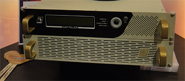
Linear showed the ATG20P ATSC Gap Filler and announced a deal with Teamcast to manufacture Teamcast’s GFX-0300 repeater module at Linear’s new plant in Brazil. As with Axcera’s gap filler, Linear’s ATG20P works with a coupling ratio of –1 dB.
In a presentation to the Ohio Association of Broadcasters, Linear Vice President of Sales Perry Priestley provided additional specifications. Required receive level is nominally –57 dBm with a range of –40 dBm down to approximately –75 dBm. MER degradation is less than 2 dB. The delay through the unit varies depending on required adjacent channel selectivity. When adjacent channels are present, the transit delay is 6 microseconds. Linear’s gap filler supports output powers up to 30 watts.
HUTECH21 EDOCR
Hutech21 had some of the most interesting DOCRs in their small booth in the back of the Korean Pavilion. Their DOCRs operate at power levels from 60 mW up to 100 watts. According to Hutech21, feedback signal-canceling technology allows the 20–100 watt DOCRs to cancel a feedback signal that’s 20 dB stronger than the desired signal.
This means that for a given receive signal and amount of receive/transmit antenna isolation, the output power can be significantly higher than with the Axcera and Linear gap filters.
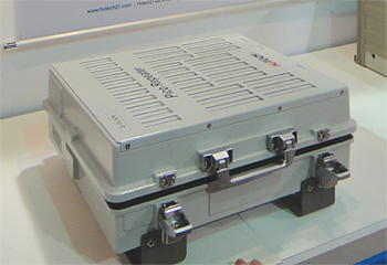
The 60 mW unit comes in a weatherproof enclosure designed to be mounted outdoors. It can repeat up to 5 channels anywhere in the current 228 MHz wide UHF broadcast band if a broadband antenna is used. Cell phone companies have found micro-cells and repeaters are necessary to provide coverage in locations like subway platforms and large shopping malls. Broadcasters will need to do the same to provide ubiquitous mobile DTV service. I can see using a unit like this mounted on the roof of a building feeding antennas inside or mounted to a light pole above a subway station feeding antennas on the platforms.
The website, www.hutech21.com, did not have any information on ATSC products when I checked in May. The company has experience in building repeaters for wireless broadband and shows Sprint and Clearwire as customers. That experience could be useful in helping broadcast engineers design systems for indoor coverage.
Hutech21 didn’t provide detailed information on the feedback signal-canceling circuitry, but I suspect it is similar to the method described in the paper “Feedback Cancellation with a Pilot-Free Reference for ATSC Terrestrial DTV Repeaters” co-authored by Ki-Hwan Suh, Young-Jun Lee, and Hyoung-Nam Kim at Pusan National University and Sung Ik Park, Ho-Min Eum, and Heung Mook Kim at the Electronics and Telecommunications Research Institute (ETRI) in Korea. The paper was presented at the IEEE Broadcast Symposium last October and is available in the proceedings.
DOCR SYSTEM DESIGN
DOCRs provide a way to fill in coverage in locations shadowed by terrain or buildings. In my November 2, 2009 RF Technology column I showed how a DOCR could improve ATSC reception in downtown Los Angeles. That hypothetical system used a transmitter with 20 watts output and an effective radiated power of 473 watts. Let’s calculate how much isolation will be required between the receive and transmit antennas.
Using SPLAT to calculate the path loss and received power, I found that KNBC should place a –30 dBm signal into a dipole at the top of the Arco Tower, the location of the repeater. We will want to use a highly directional antenna to minimize pick up of the transmitted signal and of reflections from surrounding buildings.
For this example, we’ll assume a gain over dipole of 13 dB, resulting in a –17 dBm signal at the antenna. Even after subtracting 3 dB for line loss, at –20 dB the signal at the input of the repeater will be much higher than the –57 dB level recommended. Add a 30 dB attenuator to drop it to –50 dBm.
In this example, the output of the DOCR is 20 watts, 43 dBm. Antenna gain, after subtracting line loss, is 13.74 dB, resulting in a maximum effective radiated power of 56.74 dBm (473 watts).

Linear-ATG30P ATSC Gap Filler First, calculate the gain through the DOCR. With –50 dBm in and +43 dBm out, DOCR gain is 93 dB. Adding the 30 dB attenuator on the input drops it to 63 dB.
Next add in the antenna gain minus line loss. Receive antenna gain, after subtracting 3 dB cable loss, is 10 dB. Adding the 13.74 dB of transmit antenna gain results in a total gain of 23.74 dB, increasing the required isolation to 88 dB for a feedback level equal to the received signal.
Because the received signal can fade, the repeater system must be designed with sufficient margin. The HT-DOCR5U manual recommends 15 dB. For the Axcera or Linear DOCRs, the feedback signal must be at least 1 dB below the received signal. Adding 15 dB for margin, these units will require 104 dB of isolation. Due to its feedback-cancellation circuitry, the Hutech21 HT-DOCR5U repeater will work with feedback signals 20 dB above the received signal. After subtracting the 15 dB of margin, 83 dB of isolation will be needed in our hypothetical configuration.
Fortunately, it is possible to achieve this much isolation. Reviewing papers presented at IEEE on DOCRs I found the Communications Research Centre Canada (CRC) low-power DOCR tests were done with antenna isolation around 85 dB. In Perry Priestley’s paper mentioned earlier, the DOCR test configuration in Baltimore had 110 dB isolation between antennas. Directional antennas have deep nulls. Careful positioning of the transmit and receive antennas will significantly increase isolation.
As mobile DTV grows in popularity, viewers will want to watch it in locations TV transmitters don’t reach today. The potential market for digital on-channel repeaters is huge. For example, consider five stations in the top 50 markets that roll out mobile DTV. It is likely at least 10 locations in each of those markets will need a either a DOCR or translator (assuming frequencies are available). This works out to 2,500 repeaters. In reality, large markets are likely to need more than 10 repeaters and more than five stations (assuming the FCC hasn’t taken away all the spectrum) are likely to be transmitting MDTV. In this scenario, the number of repeaters required at all power levels could increase to 10,000 or more, assuming one repeater per channel per location!
Distributing signals indoors is a lot different from transmitting at high power from a single stick. Fortunately wireless carriers have already had to deal with this and I suspect there is a lot we can learn from them. I’ll have more on indoor repeaters in future columns.
Comments are welcome! E-mail me atdlung@transmitter.com.
Get the TV Tech Newsletter
The professional video industry's #1 source for news, trends and product and tech information. Sign up below.

Doug Lung is one of America's foremost authorities on broadcast RF technology. As vice president of Broadcast Technology for NBCUniversal Local, H. Douglas Lung leads NBC and Telemundo-owned stations’ RF and transmission affairs, including microwave, radars, satellite uplinks, and FCC technical filings. Beginning his career in 1976 at KSCI in Los Angeles, Lung has nearly 50 years of experience in broadcast television engineering. Beginning in 1985, he led the engineering department for what was to become the Telemundo network and station group, assisting in the design, construction and installation of the company’s broadcast and cable facilities. Other projects include work on the launch of Hawaii’s first UHF TV station, the rollout and testing of the ATSC mobile-handheld standard, and software development related to the incentive auction TV spectrum repack. A longtime columnist for TV Technology, Doug is also a regular contributor to IEEE Broadcast Technology. He is the recipient of the 2023 NAB Television Engineering Award. He also received a Tech Leadership Award from TV Tech publisher Future plc in 2021 and is a member of the IEEE Broadcast Technology Society and the Society of Broadcast Engineers.
