Avoiding Built-In Equipment Noise Problems

As audio systems designers, we often need to track down unexpected hums and buzzes in our systems that, despite our best efforts, crop up.
We tend to look for external causes, but how many of us suspect the actual equipment itself?
Indeed, there are many ways noise problems can be inadvertently built into equipment, as Bill Whitlock, president and chief engineer of Jensen Transformers, pointed out in one of his informative presentations at the 131st AES Convention in New York.
But it doesn't have to be this way if equipment designers heed Whitlock's key points.
Any piece of gear has to work in the real world; installed as part of a total system; interconnected to other devices by signal cables and power lines; and affected by electrical and magnetic fields and radio frequency interference (RFI).
As Whitlock said, "analog signals accumulate noise as they flow through a system." Given that, it's important to do all one can to keep noise from entering the signal path in a device in the first place.
BALANCED INPUTS/OUTPUTS
Since most noise enters at the signal interfaces, they need to have high noise rejection. Since unbalanced interfaces have no inherent noise rejection, start by keeping all inputs and outputs balanced.
"The balanced interface is the ultimate in noise prevention," Whitlock said. Balanced circuits have the ability to cancel out a signal, like noise, that is common to both signal inputs (high/low or plus/minus), while allowing the desired differential signal to get through.

Bill Whitlock Common-Mode Rejection Ratio (CMRR) is the measure of how well the common-mode signal is cancelled out, measured as the ratio of the differential to common-mode gain and expressed in dB.
CMRR of an entire interface depends on common-mode impedances—matching at the driver's output; matching at the receiver's input; and perhaps most importantly, how high the impedances are at the receiver.
In real-world circuits, impedance mismatch or "imbalance" at driver outputs is commonly 10 ohms (Ω) or more. According to Whitlock, common-mode impedances for typical conventional active input stages range only from 5 kΩ to 50 kΩ at 60 Hz. This means even a small mismatch at a driver output can significantly reduce CMRR.
Whitlock noted that a widely used balanced line receiver integrated circuit (IC) loses 25 dB of CMRR with a source imbalance of only 1 Ω.
A solution, then, is to design the input stage to have a very high common-mode impedance. This can be accomplished by using a good audio transformer (an impedance of 50 MΩ is fairly typical), which makes them much more tolerant to impedance imbalances. Even with this advantage, however, transformers have fallen out of favor in audio circuit design.
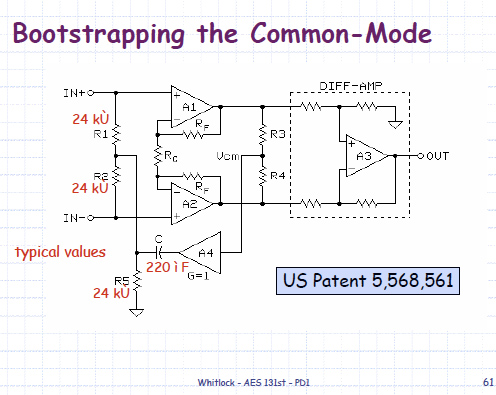
So, for those who prefer an IC solution, Whitlock designed and patented a circuit that uses the bootstrapping technique to provide higher impedances using op amps, (see Fig. 1). According to Wikipedia, "a bootstrap circuit is an arrangement of components used to boost the input impedance of a circuit by using a small amount of positive feedback."
Whitlock's design also incorporates RFI suppression, and, among other features, is designed to perform better than other circuit configurations in receiving signals from unbalanced outputs. For those who are interested, look up patent number 5,568,561, where a full description can be found.
THAT Corp. produces an IC based on Whitlock's design, the THAT 1200-series InGenius balanced line receiver IC, which can be used instead of more common op amp balanced circuitry, or as a drop-in replacement for other receiver ICs.

Fig. 1: An example of a bootstrapping circuit to provide a high common-mode rejection ratio, as designed and patented by Bill Whitlock, Jensen Transformers. Courtesy of Bill Whitlock As CMRR is so important, it's also important to measure it correctly. Whitlock proposed a test procedure that takes into account the output impedance inbalances of real-world equipment. This procedure was adopted in August 2000 as IEC 60268-3.
With this method a 10 ohm resistor is switched first in one input leg for one measurement of CMRR; then in the other leg for a another CMRR measurement. The worst of the two values is the one that's predictive of real-world performances. Earlier methods could give a false impression that CMRR will be better than it actually is when interconnected with other equipment.
PROBLEM-SOLVING
Another problem that should be avoided is the "pin 1" problem, where shield current is allowed to flow in the signal reference traces or wires inside the box, thus adding noise to the desired signal. Use a star grounding (reference) system for the device, keeping the shield current in a path that's separate from the signal reference.
For inputs and outputs, connect the shield pin of the connector to the star point, or chassis, if present. The idea is to give the shield current, which generally consists of power-line-derived noise, its own separate pathway to the chassis (and safety ground, if present); and preventing it from contaminating the signal reference ground.
To help reduce RFI, enclose sensitive circuitry in a metal enclosure, and if needed, use small holes instead of slots for airflow. According to Whitlock, use RFI filters of appropriate topology and bandwidth to minimize the impact on ACMRR at balanced input and output ports.
Avoid creating magnetic and electric fields inside the device that may induce fields into the signal lines. As Whitlock suggested, use a power transformer with a low flux-density design, rated for at least 120–200 percent of actual line voltage. This keeps the transformer far from magnetic saturation. Tightly twist the primary and secondary wires. Use fast recovery rectifiers and bypass capacitors across them.
Keep the transformer secondary, rectifier and storage capacitor loop as small as possible. In addition, keep signal lines away from the power supply and AC line wiring and twist signal wires or traces or keep them close together. If necessary, shield signal wires or traces.
It's hoped that these suggestions will prompt equipment and circuit designers to delve deeper into this subject; evaluate their products and new designs; and make necessary changes to minimize noise problems originating in the box. What a good New Year's resolution.
Mary C. Gruszka is a systems design engineer, project manager, consultant and writer based in the New York metro area. She can be reached via TV Technology.
Get the TV Tech Newsletter
The professional video industry's #1 source for news, trends and product and tech information. Sign up below.
