Broadcast DTV
To begin, one should wonder whether the headline scenario is possible. Should the industry even look into it? The answer is yes, it is possible.1
Why is the DTV Transmitter-Receiver link model, made up of a rooftop antenna connected to an ideal receiver, a path without multipath that ignores diffraction loss at the radio horizon and ground clutter loss all around? The simple answer is that this model, a relic of 1950s analog television, was the only way to satisfy (only on paper) the demand from some broadcasters that digital HDTV reception be extended to the then analog Grade B contour. I can make this observation because I participated in the ACATS proceedings. The objective was clear: We needed an American DTV standard, fast. Broadcasters, not in a position to analyze true limits of the ATSC 8-VSB system, got the promised “coverage area” assurance they sought, and a new standard was off and running.
It didn’t take long to realize, experimentally and theoretically,2 that the ATSC standard was unsuitable for reliable reception by consumer devices with a rooftop antenna or even aided by DTS.
We now have the opportunity to do it in a way that will promote the growth of free OTA DTV before it succumbs to other wireless competitors with advanced capabilities.
Service or coverage
The service area is not the thermal-noise-limited contour used by the FCC to predict “coverage area” to well beyond the radio horizon, at which diffraction loss predominates and where solid reception by typical consumer installations was unlikely even in the analog-TV era. For DTV, service is important, not coverage. The decodable payload in the presence of multipath and interference quantifies the service, whereas coverage simply quantifies the incident signal without multipath and without interference. That was OK in the analog era because video and audio were never lost, just gracefully degraded. But, for DTV, service rather than coverage is of value, and the real service area is clearly limited by the radio horizon. The residual signal beyond the horizon may be a minor interference to the few who insist on reception in that area, but that should be of secondary interest to broadcasters. So, before we continue, we must accept this technical reality.
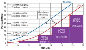
Figure 1. This shows what can be done, in principle, trading payload for SNR.
Who wouldn’t want graceful degradation of DTV to replace the black screen? That would be one of several possibilities with a new standard. Look at Figure 1 for what can be done in principle3, trading payload (Mb/s) for SNR (dB). Note how the capacity decreases with SNR, which in turn decreases with distance from the tower. The ATSC system was designed for SNR = ~15dB at the noise-limited contour. So, the maximum payload was set to ~20Mb/s, exhibiting a “cliff-edge” for lower SNR. But, as experience has shown, ATSC service is greatly impacted by real-world multipath. That’s why it is not unusual for many consumer receivers within the coverage area to display pixellation or frozen video. With multicarrier (COFDM) hierarchical modulation, graceful degradation from high to low payload is one of several possibilities.
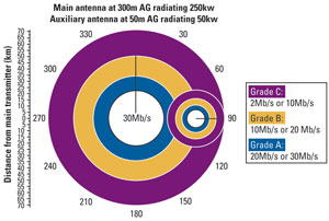
Figure 2. Higher payload up to the radio horizon is possible through low-power auxiliary transmitters on adjacent channels, each serving two main stations at half bit-rate.
Better yet, how about higher payload up to the radio horizon? That too would be possible by adding low-power auxiliary transmitters on adjacent channels, each serving two main stations at half bit-rate. In effect, each broadcaster would be getting 9MHz of bandwidth. This is not an SFN, and no synchronization of transmitters is required. (See Figure 2.) There could be several auxiliaries on the same adjacent channels so long as they are shielded from each other by their radio horizons. Figure 2 was computed just to explain the ideal Quality-of-Service (QoS) contours using F(50,90) without interference and multipath.4
The DTV channels are now sparsely spaced, and OET-69 applies to only one interferor, the first adjacent channel. For packed channels, OET-69 is useless as it cannot be “fixed” for multiple interferors emanating from different antennas on different towers. To achieve spectral efficiency through closely packed channels, the FCC will have to mandate minimal specification on the linearity and dynamic range of the receiver, the weakest link between the broadcaster and the consumer, and also mandate SNR-controlled AGC.
Channel repacking example
Most broadcast television markets can accommodate up to 12 full-power stations. However, a market may require 16 or more stations. One possible example of allocating 16 main and eight auxiliary low-power stations occupying 144MHz is shown in Figure 3. The main channels are grouped in pairs, in part because the popular and effective slotted-pipe antenna can accommodate two UHF channels. In the depicted allocation, Channels 23 and 26 receive the worst interference, mostly generated by the receiver’s non-linearity.
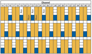
Figure 3. In some situations, a market may require 16 or more stations. This is an example involving 16 main and eight auxiliary low-power stations.
There are seven interference components that must be accounted for in state-of-the-art receivers where the tuner is on a silicon chip and without inductive elements. These components include those from certain pairs and triplets of channels. The QoS contour map of Channel 23, including multipath and six of the seven sources of interference generated by the main and auxiliary transmissions,5 is shown in Figure 4. The receiver’s linearity used for these results is comparable to that of a “good” existing DTV converter box.
Toward the East, Channel 23’s SNR is degraded by Channel 22. In that area, the receiver can switch to Channel 22 at half rate and high SNR, which extends to the radio horizon.
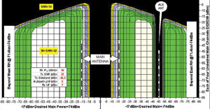
Figure 4. This shows the QoS contour map of Channel 23, including multipath and six out of seven sources of interference generated by main and auxiliary transmissions.
One can add more interference or change the locations of the various towers and the transmitting antenna’s patterns. These changes may shrink the high SNR contour and move the operating point on the SNR plot. But, as long as the carrier’s pilots are detected, the SNR-controlled AGC then moves the operating point toward the area of maximum SNR. For a known modulation, the SNR contours are interchangeable with payload contours, and, for a given ERP and propagation algorithm, the X-axis can be converted to distance away from the tower. Thus, a complete prediction of service in the presence of multipath and interference is possible.
Footnotes:
- You can read more about it in my filing with the FCC, docket 12-268: http://apps.fcc.gov/ecfs/document/view?id=7022117651
- “Why are the ATSC-8VSB and M/H Standards Fundamentally Unsuitable for Next Generation Television Broadcasting and How to Painlessly Transit to ATSC/OFDM Network.” Available at http://www.tvantenna.tv/papers.asp
- I. Eizmendi et.al., “CNR requirements for DVB-T2 fixed reception based on field trial results,” Electronics Letters, Vol 47, Issue 1, 6 January 2011. Data scaled to 6MHz channel.
- A paper titled “Spectrally Efficient DTV System: A step-by-step Design of 1MW UHF System for Reception by Hand-held Devices up to the Radio Horizon,” is in progress.
- The seventh, triple beats, requires statistical approximation and is under review.
—Oded Bendov is president, TV Transmission Antenna Group.
Get the TV Tech Newsletter
The professional video industry's #1 source for news, trends and product and tech information. Sign up below.
