Can LED Strip Lights Offer Improved ‘Evenness’?
Strip lights have been around for a long time. All sorts of linear arrangements come to mind—from rows of candles (every foot?) to reflector flood lamps (R40s, of course) to present-day LED strip-light fixtures. Their general use is to evenly light a vertical surface by placing the fixtures parallel to the surface, at the surface’s bottom or top, or at both the bottom and top.
A very typical, traditional situation is the lighting of a background to represent the sky, usually a seamless cloth drop known as a “cyclorama.” Various combinations of gradations, brightness and color of our sky may come later, but, for now, we will only deal with the basic use.
GREAT MINDS
A few weeks ago, I attended an informal equipment demo at a sound stage in Los Angeles. One of the fixtures shown was an improved version of an LED strip light to which two additional colors, white and amber, had been added to the three (RBG) of the first-generation iteration of the unit. We only had one unit.
All the lighting professionals in our small group had an experience to relate about their personal “cyc” lighting attempts. The stories were very similar.
We all had been schooled on the use of a floodlight fixture using a linear tungsten lamp designed with an asymmetrical reflector to obtain evenness. Everyone agreed that the arrangement of fixtures placed at the top and bottom only came close to getting the proper result—particularly at a height of, say, 30 feet. There always seemed to be a dark “middle.” But, worst of all, the required power could be 500 watts per foot per color.
We were all eager to use the improved LED strip light for this application because of the low-power draw of these units and the promise of better, greater efficiency; and, of course, an unlimited palette of colors. We also knew from experience that, due to the narrow and round beam from the LED strip light, there would be a “dark” area at the bottom.
Because of this, we also suspected that a double row would be necessary on the bottom, but not necessarily on the top.
UNCERTAINTY

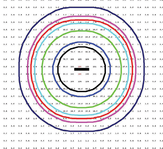
Fig. 1: Iso-Footcandle Diagram--Strip on Normal Axis The demo came to a standstill. Even with the combined imagination and experience of the group, no one could say with certainty what the configuration of the LED strip lights would have to be in order to satisfy the evenness criteria.
At this point, I want to outline the characteristics of the LED strip light. Fig. 1 shows the pattern from a 24-inch strip light located on a normal axis aimed directly at the center of a vertical wall. The lines about the center are points at which the incident light (foot-candles) is the same value (an iso-foot-candle diagram).
Visualize a lot of light meters placed flat on the wall with their discs straight ahead, all reading at once. This diagram shows that the pattern is symmetrical about the lamp’s axis, very much like a spotlight.
Realizing that this narrow spread is very limiting, the manufacturer provides auxiliary plastic lenses that can spread this pattern wider and, in most cases, achieve the symmetrical shape of the pattern shown. The natural beam angle without a lens happens to be 11 degrees. The auxiliary lenses of 22 and 34 degrees provide wider beam spreads.
NO CYC AVAILABLE

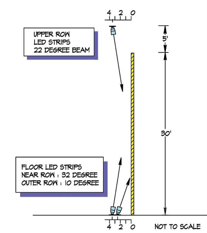
Fig. 2: Side View of Test Set-up I should mention how I obtained the preceding diagrams. I would guess that you realize there was no way I could actually take incident light measurement on the wall surface shown, which is 30 feet wide and 30 feet high. Even if the space were available, taking all the readings at all the necessary points would be a time-consuming process.
However, the LED strip-light manufacturer has provided IES files for the unit. These are files that provide candlepower values in a specific format as dictated by the Illuminating Engineering Society, and are usually obtained by the manufacturer from specific testing laboratories unique to this field. These files, in conjunction with appropriate software, are used by lighting engineers and consultants (usually in the architectural field) to calculate all sorts of lighting data. I used a very popular software program to obtain the incident light values that are shown. No studio was required.
CALCULATING

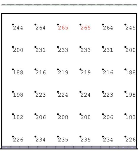
Fig. 3: Calculated Footcandles--Best Set-up The problem, therefore, was to determine a configuration of strip lights that would evenly light a 30x30-foot vertical surface.
The most successful setup is shown in Fig. 2 with the calculated results shown in Fig. 3, a front view of the wall. As you can see, two rows—one wide beam and one very narrow beam—were required on the bottom, and one narrow at the top.
The performance of the top row of strip lights is aided by the fact that it is located an appreciable distance above the top of the wall, which is impossible at the bottom. I found the slight differences in the values of the individual calculated points to be quite unexpected.
Before you join in the festivities celebrating such a positive result, I would like to point out a few restraints. I found that the results were very sensitive to the tilt angles, as well as to the distance from the wall to each row. In addition, the IES data used to calculate was measured with all five color channels full.
And, most importantly, the results were obtained by calculation only. In addition, the calculation does not take into account where the fixture is close to surface and the candlepower/distance relationship is not valid. So, for absolute confirmation, we need to find 90 feet of LED strip lights, a studio with a 30-foot cyc (and 35-foot-plus grid) and a group of volunteers. I’ll get back to you.
Bill Klages would like to extend an invitation to all the lighting people out there to give him your thoughts at billklages@roadrunner.com.
Get the TV Tech Newsletter
The professional video industry's #1 source for news, trends and product and tech information. Sign up below.
