Checking Out TV Antennas With a $130 VNA
Vector network analyzers (VNAs) are amazing tools that not only let you check an antenna’s VSWR (and return loss) over frequency, but also display the complex impedance of the antenna. Some can be used as a time domain reflectometer (TDR) to determine the length of a coax or transmission line, or to determine the distance to the fault in a line. Two port VNAs can display filter response and return loss.
AFFORDABLE VECTOR NETWORK ANALYZERS
Such versatile tools have been quite expensive. Even a basic analyzer from Copper Mountain Technologies, one of the most popular brands of VNA, costs well over $2,500 and that’s before adding a calibration kit. I was surprised when I was checking out WVIT’s new post-repack transmission facility in Hartford, Conn., and consulting engineer Joe DiMaggio told me about a VNA he found that cost about $350.
He compared his miniVNA with a professional VNA and found it surprisingly accurate.
I immediately ordered a miniVNA Tiny Plus2 similar to his from China. The unit arrived in a nice case with cables and SMA calibration kit. I downloaded the required Java-based software from http://vnaj.dl2sba.com. This VNA covers 1 MHz to 3 GHz and the software offers a number of options for typical one and two port VNA measurements for checking antennas, filters, cable loss, amplifiers, etc. The TDR function is limited to determining the length of a coaxial line. The miniVNA Tiny Plus2 kit was a bit big, however, for packing in my travel kit.
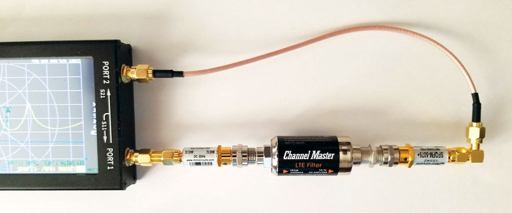
While searching for software for the miniVNA I came across the NanoVNA analyzer (Fig. 1). The original units have a 2.8-inch LCD screen and are about 54x85.5x11mm in size. Frequency range is 50 kHz to 900 MHz. I bought one for $53 from Amazon (shipped from China). These VNAs use an open source hardware design and quality varies greatly. Some units don’t even shield the RF components, and while most come in a plastic box with the calibration kit and cables, the VNA itself is just a stack of the metal back plate, circuit board and LCD with the sides open. Based on reviews I’ve seen online, the cheap units that have a replica of the Copper Mountain lizard logo on them are the worst. Amazon prices have gone up due to tariffs, but most are still under $75.
While searching for a case I found an improved version of the NanoVNA on eBay. This unit has a 4.3-inch LCD display, full metal case, and claims a 1 GHz upper frequency limit. Search eBay for “NanoVNA VNA HF VHF UHF Vector Network Antenna Analyzer + 4.3 LCD + Metal Case” to see the offerings. The price is around $125, direct from China. I recommend choosing a top-rated seller. The 4.3-inch NanoVNA, along with the nanovna-saver software (https://github.com/mihtjel/nanovna-saver) is what I used in this article.
In addition to the measurements available in the miniVNA’s software, nanovna-saver also includes an X-Y TDR display that can show discontinuities in the middle of a cable as well as cable length. The program is Python-based and available as a binary file (currently nanovna-saverv0.2.0. exe) for Windows and a simple installer script for Linux. It works with both the 2.8-inch and 4.3-inch versions of the NanoVNA. Since the NanoVNA includes a display, a computer and software isn’t required, but will provide additional measurement options (like TDR) and segmented sweeps (for greater resolution) and the ability to save parameter data in standard format (s1p, s2p) and plot graphs.
Before you get too excited about these low-cost VNAs, there are some significant limitations. The maximum output power is around –9 dBm for the NanoVNA and –6 dBm for the miniVNA. Available software doesn’t appear to have an option to eliminate interference from the strong signals likely to be present at a broadcast antenna site. I suspect they wouldn’t last long connected to an 8-inch transmission line feeding an antenna on a shared tower. The accuracy will depend on the accuracy of the open, short and load used to calibrate the VNA.
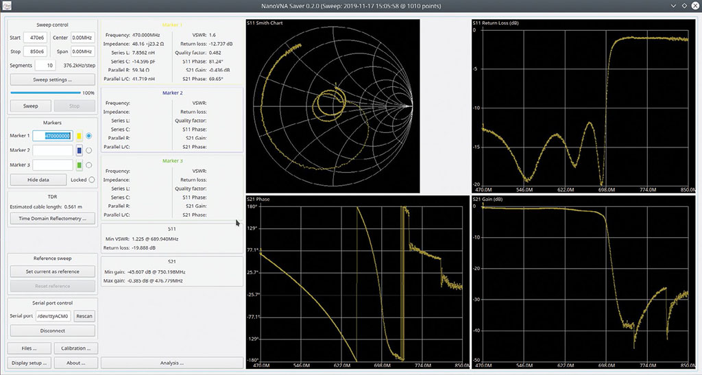
Even with these limitations, I find the NanoVNA useful and worth packing in my travel kit. Fig. 1 shows a test setup I used to measure a Channel Master LTE filter; Fig. 2 shows the results. For this measurement I used minimum loss 50 ohm to 75 ohm pads to present the proper impedance to the filter and calibrated the VNA at 75 ohms with a homemade 75 ohm cal-kit. As you can see, the drop off above 698 MHz is quite steep, but we’ll need a new version that cuts off frequencies above 608 MHz once the incentive auction repack is finished next year as I’m already seeing strong cellular signals popping up in the new 600 MHz wireless band.
TESTING INDOOR ANTENNAS
I tested a few antennas using the NanoVNA calibrated with my 75-ohm cal-kit on the output of the RG-6 coax to the antenna. For antennas, the 50 to 75 ohm pad is not necessary if VNA is calibrated using the 75-ohm cal-kit. I found my vintage Mohu Leaf, which has traveled in my suitcase with cables of various sorts for more than five years, apparently now has some broken connections as its return loss was a flat 2 dB across the 470–608 MHz band.
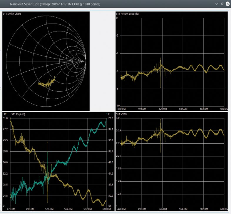
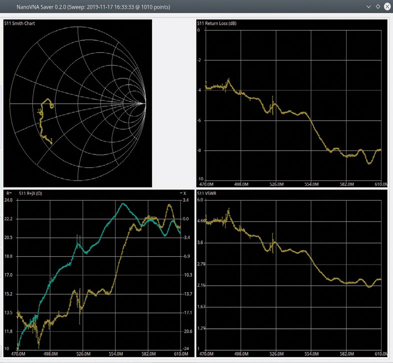
I ordered a new Mohu Leaf 30 and will report on how it works. I tested a gigantic Mohu Leaf Glide 65 (without preamp) designed for VHF and UHF and found, as expected, it had decent return loss (Fig. 3) across the repacked UHF band. The Winegard Freevision FV30-HD had good return loss in the mid-band channels, but return loss increased at the lower UHF channels. Fig. 4 shows the Winegard antenna after I shortened the balun leads. I found that with the full-length leads, the performance was worse. Without the VNA, I would have never noticed this.
I needed a thin antenna to replace the Leaf while waiting for the new one to arrive. I found an Onn ONA19CH002 Indoor TV Antenna for only $16.88 at Walmart. The antenna is transparent so the antenna element is clearly visible. It worked well in the four cities I tested it in (Miami and Tampa, Fla., Hagerstown, Md. and Los Angeles).
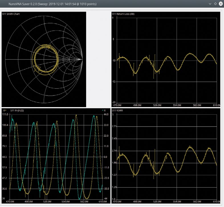
Unfortunately the thin coax cable is permanently attached to the antenna so I was only able to measure the return loss with the cable included. Fig. 5 shows the result using the NanoVNA calibrated with my 75-ohm cal-kit. The sine wave-like variations in the return loss and VSWR plots are due to coax cable and return loss overall is reduced by losses in the cable.
DIGITENNA ANTENNAS
I mentioned the DigiTenna a year ago when describing the setup Meintel Sgrignoli Wallace (MSW) uses for field measurements, (Indoor Antennas, Field Measurements Revisited, January 2019). While I was in Chicago in November for some signal testing DigiTenna owner Brad Eckwielen visited WMAQ-TV and showed us his range of antennas. I had my NanoVNA with me so we also did a number of measurements on the antenna.
I was impressed with the performance of the antennas, which are much simpler than many of the common antenna designs. The key element in his antenna is a driven element that looks like a solid bowtie, but somewhat bigger than those seen on UHF antennas.
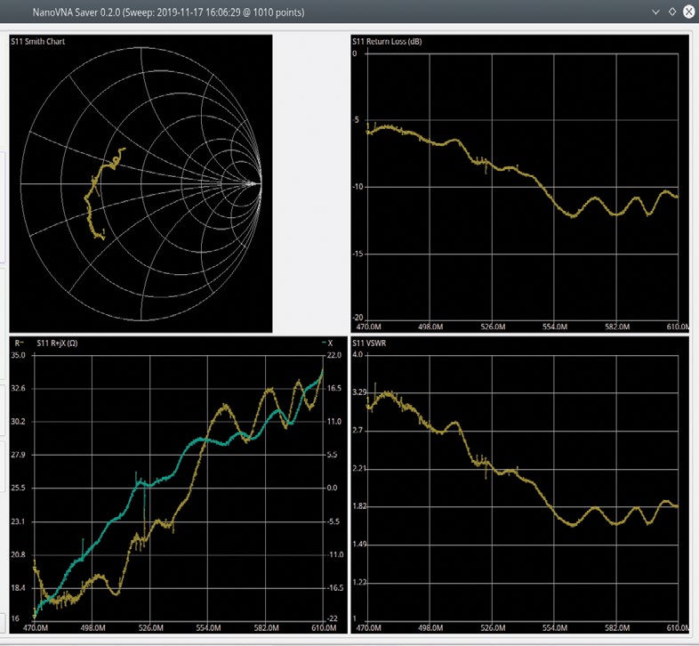
Eckwielen put a lot of effort into obtaining a good match from the 75-ohm coax to the antenna, and has modified the shape of the element to provide good results on both UHF and VHF. The DT-31 element I tested is the current design and optimized for the full 470–698 MHz UHF band. As you can see in Fig. 6, the return loss at the low end of the UHF band isn’t as good as at Channel 36. Newer DigiTennas will be designed for better return loss over the new, narrower, 470–608 MHz band.
Higher gain versions of the antenna add a corner reflector for UHF and a reflector element for VHF as well as directors. A version with a low-noise preamplifier built into the matching assembly at the feed point is available for very weak signal areas. One of the engineers at WMAQ-TV plans to compare a mid-range DigiTenna with his Winegard HD8200U monster antenna. If he shares the results, I’ll share them in a future column.
DigiTennas are primarily available through authorized distributors/installers, but TV station engineers can contact him directly. One distributor is a1 Components (www.a1components.com). Because these antennas are made in Wisconsin, not in China, don’t be surprised at the price—often more than double that of Chinese-made antennas.
RESCA REVISITED
A reader pointed out that I missed a rescan tip in my last column (Phase 4 and More, Surviving the Repack, August 2019). The direct-tune (RF Channel. Program Number) method won’t work on many sets if the channel is already in the receiver’s memory. For some receivers, the memory can also prevent the tuner from finding changed channels.
The solution for both these problems is simple. Clear the TV set’s memory by doing a scan with no antenna selected; verify no channels are listed; then scan (or direct-tune) to get the updated channels.
As always, I welcome your comments and questions atdlung@transmitter.com. Let me know if you are interested in VHF impedance plots of these antennas. Responses may be delayed if I’m busy, bug me again if you don’t get an answer in a week or two.
Get the TV Tech Newsletter
The professional video industry's #1 source for news, trends and product and tech information. Sign up below.

Doug Lung is one of America's foremost authorities on broadcast RF technology. As vice president of Broadcast Technology for NBCUniversal Local, H. Douglas Lung leads NBC and Telemundo-owned stations’ RF and transmission affairs, including microwave, radars, satellite uplinks, and FCC technical filings. Beginning his career in 1976 at KSCI in Los Angeles, Lung has nearly 50 years of experience in broadcast television engineering. Beginning in 1985, he led the engineering department for what was to become the Telemundo network and station group, assisting in the design, construction and installation of the company’s broadcast and cable facilities. Other projects include work on the launch of Hawaii’s first UHF TV station, the rollout and testing of the ATSC mobile-handheld standard, and software development related to the incentive auction TV spectrum repack. A longtime columnist for TV Technology, Doug is also a regular contributor to IEEE Broadcast Technology. He is the recipient of the 2023 NAB Television Engineering Award. He also received a Tech Leadership Award from TV Tech publisher Future plc in 2021 and is a member of the IEEE Broadcast Technology Society and the Society of Broadcast Engineers.
