Commemorating The PAR Can Fixture

It was of great interest to me that two of last month's entertainment production periodicals featured articles celebrating the lowly, but certainly loved, PAR Can fixture. The articles (one by Richard Cardena and the other by Rob Halliday, both very talented friends) credited the legendary lighting designer Chip Monck with creating the popularity of this simple lamp in the live-performance concert world.
It should be added that, prior to this, it was common practice in film—and television—to boost the voltage on the 500 watt, 2850° K lamp to make it equivalent to a 3200° K or 3400° K lamp and to get nearly 50 percent more light output. Of course, the life of the lamp was greatly shortened.
The availability of the 1,000-watt, 3200° K, PAR-64 in four-beam configurations has eliminated the need for the auxiliary boost unit and gained industry-wide acceptance.
In television, a great step forward was the realization that efficient wiring systems and methods were available from concert equipment suppliers, and that a few hundred of these very efficient fixtures could be employed for such brute-force applications as lighting audiences, multicolor washes and even graduated cross lighting from ladder positions.
A few narrow-spot PAR Cans would put out more beam lumens than a 5 kW Fresnel fully spotted at a long throw distance (say, 100 feet). Things like six-circuit multicable and bars with six PAR heads provided great convenience.
However, one incident early on made me more conscious of a problem that could exist even in such a simple load distribution scheme. I was lighting a beauty pageant in an arena in Honolulu. At the time there was very little equipment available on the islands and I had shipped a system from Los Angeles, much of it supplied by a concert rental house.
I recall that, for some reason, I had lined a perimeter catwalk in the arena ceiling with a number of six-light bars, wired with multicable and fed from dimmer racks located at floor level. When I started to focus, it was very apparent that there was a problem with voltage drop due to the lengths of the multicables.
As you followed the cable path from bar to bar, the lamp color became more and more orange. Even today when our attention may be diverted to a more vexing challenge as to how to employ an LED fixture, this situation can still exist. I would like to review these very basic issues.
THE BASICS

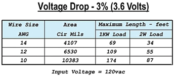
Fig. 1: Maximum cable run from dimmer to fixture for 3 percent voltage drop Cable has electrical resistance; the thicker the cable, the less its resistance. As the current flows to our lamp by an amount determined by the actual voltage across the lamp, there is a voltage loss due to the cable's resistance.
The light output from an incandescent fixture is very sensitive to the applied voltage. As an illustration, a lamp intended to be used at 120 Volts will have half the light output at about 96 Volts. This is only a 20 percent voltage drop.
Note: This would also amount to about 200° K lower color temperature. In the case of a photographic lamp that's specified to operate at 3200° K, it would then be operating at about 3000° K.
So it's important that, if we are interested in making our system performance efficient, we should limit this voltage drop. But, we are limited to the wire size that is available to us by what the supplier has in inventory.
In the case of multicable, it is either #12 or #14 American Wire Gauge (AWG), with #12 being thicker. A greater cross-sectional area has less resistance; hence, a lower voltage drop than #14 AWG. (Note: There is some #10 AWG multicable, but unfortunately it's very rare.)
VOLTAGE DROP LIMIT
Next, we have to set a realistic voltage drop that we will accept. Looking to the National Electrical Code (NEC) for guidance, it suggests a 3 percent voltage drop limit. At 120 Volts this would be 3.6 Volts.
At this voltage, our lamp will have approximately 90 percent of the light output at the proper voltage. For practical reasons, this should be considered acceptable.
I have provided a table (Fig. 1) that lists the maximum cable run from the dimmer to the fixture, which would be needed in order to provide the 3 percent limit under different possible alternatives. A 2 kW load would have two PAR-64s "two-fered" as a load while a 1 kW load would be one lamp. Note that the lengths are not very long.
ABOUT THE SUPPLY VOLTAGE
In order to meet the requirement that we start with a feed of 120 Volts to realize the criteria detailed above, the dimmer rack output must deliver 120 Volts at each dimmer output when "full."
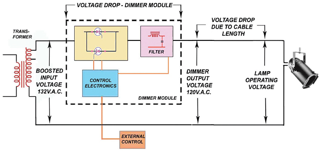
The rub here is that there is also a voltage drop in each dimmer module due to a voltage loss through the solid-state device, an SCR in most cases, as well as a drop when current flows through the filter choke in each dimmer. (See Fig. 2)

Fig. 2: Lighting distribution circuit voltages
To eliminate these voltage losses, the dimmer manufacturers of professional grade equipment provide that the voltage output of the dimmer is regulated to 120 Volts—if the input voltage is greater than the sum of the dimmer's maximum voltage drop under rated load and 120 Volts.
It's good practice to raise the dimmer rack input voltage at the supply transformer, if possible, usually to the +10 percent tap. This will ensure that the dimmer's regulated output voltage will be equal to 120 Volts.
It goes without saying that this should be done by a qualified person. (Actually, in the case of some of the more sophisticated dimmer modules, the voltage output can be regulated at more than 120 Volts; however, this is not recommended.)
CHANGING TECHNOLOGIES
It must be emphasized that we are talking about conventional incandescent fixtures. The majority of light fixtures now are equipped with discharge lamps. In addition, there are other fixtures that are not incandescent. These include HMI and LED sources. In such cases, the individual power supply for the fixture is designed to adapt to a range of input voltages; in some instances, the range can be wide, from 100 to 240 Volts.
With any of these voltages, the power supply will regulate to deliver the correct lamp operating voltage and current. Voltage drop, therefore, is not a consideration for such fixtures, as long as the input voltage is within the operating range (and there is no limitation to the current that needs to be supplied). Some instruments that use an incandescent lamp are even equipped with self-regulating supplies.
So, treat your lowly PAR Can with respect and get every drop of light out of it as possible. Keep the voltage drop as low as possible by locating your dimmer racks as close to the lamps as possible. Boost the input voltage to your dimmer rack and set your dimmer's regulated output to 120 Volts. Use the largest wire size available and place only one lamp on each circuit. Then sit back and enjoy.
Bill Klages would like to extend an invitation to all the lighting people out there to give him your thoughts atbillklages@roadrunner.com.
The professional video industry's #1 source for news, trends and product and tech information. Sign up below.
