Deconstructing Digital Audio Subframes, Part 3

The AES3 digital audio signal is composed of frames, with each frame containing a digital sample from each of two audio channels. Each frame of an AES3 digital audio signal is divided into two subframes, one for each of the two audio channels. Each frame contains one sample word for channel one, followed by one sample word for channel two, thereby multiplexing the individual samples for the two channels into that one frame.
If there's only a single channel present, it's assigned to channel one. The digital signal can be repeated in the second channel, or the second channel bits can be set to zero. One hundred and ninety two frames (from frame zero to frame 191) constitute a block.
The frames are transmitted at the same rate as the original source audio was sampled, such as 48 kHz (typical for broadcasting), 96 kHz or 192 kHz (high-end digital audio).
Each subframe is divided into 32 timeslots, numbered from zero to 31. The first four timeslots are reserved for a special set of bits, called preambles. The next 24 timeslots (4-27) are for the bits of one audio sample.
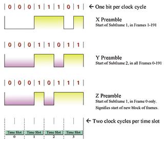
Fig. 1: AES3 subframe preambles starting with a transition from positive to negative (adapted from AES3-2003 standard) The last four timeslots carry special bits related to the audio sample that just preceded them. Timeslot 28 carries the validity bit, timeslot 29 carries one bit of the user data channel, timeslot 30 carries one bit of the channel status information, and timeslot 31 carries the parity bit.
Let's look at each of these sections in more detail.
THE FULL PICTURE ON PREAMBLES
Preambles are specific bit patterns that allow an AES3 receiver (a digital audio input on a piece of gear) to synchronize to the incoming signal and to identify when a new subframe or block occurs.
The AES3 standard allows only three preambles—X, Y and Z. Each preamble must transition to a different level from that of the last state of the bit before it. All of the preambles start with the same type of transition. If the voltage level of the bit in timeslot 31 of the previous subframe was positive, then the start of any of the preambles must transition to a negative voltage. If the polarity of the AES3 signal was reversed, then the transition would take place from negative voltage to positive.
Fig. 1 and Fig. 2 show a graphical representation of each set of preambles. One set is of the opposite polarity of the other. Because absolute polarity doesn't matter in AES3, both sets of preambles must be able to be decoded.
These preambles are transmitted in the first four timeslots, zero through three, at the start of each subframe. The X preamble starts subframe one (channel one subframe) for all frames except frame zero. Frame zero is the start of a new block of frames, so a different preamble is used, the Z preamble, to indicate both the start of a new frame and start of a new block.
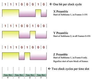
Fig. 2: AES3 subframe preambles starting with a transition from negative to positive. The polarity is opposite that shown in Fig. 1 (adapted from AES3-2003 standard). The Y preamble starts subframe two (channel two subframe) for all frames.
Unlike the rest of the bits in the AES3 subframe, the bits that comprise the preambles do not conform to bi-phase mark rules. This allows them to be distinguished from bits representing data.
Note that some of the pulses in the preambles occur over three clock cycles (one and a half time slots). For regular data, a pulse can only occur over one or two clock cycles, to represent logic "0" and logic "1" respectively. The AES3 standard refers to each of these clock cycles as a unit interval, which is the shortest time interval used for coding.
However, although the preambles do not conform to bi-phase mark coding, there are the same number of negative going pulses as positive going ones, so, like the rest of the bitstream, the preamble does not contain a DC component. The preambles also have even parity.
ONES AND ZEROS
For now, we'll skip over the timeslots four through 27, and discuss them next time.
Timeslot 28 carries the validity bit, which indicates whether the preceding bits in timeslots four through 27 can ultimately be decoded to analog audio. Logic zero in the validity bit slot indicates that the sample word is suitable for conversion to analog audio. Logic one means that it is not. The validity bit does not have a default state.
In practice, if the sample bits represent linear PCM digital audio, then the validity bit should be set to logic zero.
The Dolby E bitstream is an example of when sample bits do not represent linear PCM audio, and where the validity bit should be set to logic one. The Dolby E data bitstream contains up to eight channels of bit-rate reduced (data compressed) audio, multiplexed together, along with timecode and metadata. Its frame rate matches that of the video it is designed to accompany.
If a receiver detects a validity bit with logic one, a useful response would be to mute the audio output, to prevent the output of what could be high-level noise.
The validity bit setting should be consistent with the setting of the nonaudio bit in the channel status. There could be other instances where the validity bit is set, like if an error occurred in the linear PCM stream, or if error correction was applied to the audio output.
There could be many reasons why a digital audio receiver mutes, but if it's happening on known linear PCM audio, then verifying the status of the validity bit would be one check.
Timeslot 31 carries a parity bit that creates even parity for the bits in timeslots four to 31 inclusive. That means the parity bit will be set so that an even number of logic zeroes and an even number of logic ones over these 28 bits will result. For example, if timeslots four to 30 contain 11 logic zeroes, and 16 logic ones, then the parity bit will be set to logic zero to create an even number of 12 logic zeros in the 27 preceding timeslots plus the parity slot.
I'll cover more on channel status, and timeslots 29 and 30 next month.
Mary C. Gruszka is a systems design engineer, project manager, consultant and writer based in the New York metro area. She can be reached via TV Technology.
Get the TV Tech Newsletter
The professional video industry's #1 source for news, trends and product and tech information. Sign up below.
