Designing the IP-Based Media Network Part 2
ALEXANDRIA, Va.—Broadcast facilities are already beginning the transition from SDI-infrastructures to IP-based network-centric facilities. Many expect significant changes to occur over the next five years and beyond. Content creation, production, and distribution entities will likely shift from the traditional SDI to an IP-based network topology employing common off-the-shelf (COTS) solution sets, steeped in software defined networking (SDN). With that change, the transport and manipulation of high bit rate (HBR), uncompressed (UC) media signals—especially for live/real-time production activities—will become the “next-generation infrastructure” of our future.
Recently adopted SMPTE standards, including ST 2022-6 & -7 and ST 2110; accompanied by industry forums (AIMS, VSF, AMWA) with their own initiatives and augmentations, are the driving forces that will essentially reshape the entire broadcast facility. Buckle your seat belts, we’re all in for an exciting and innovative ride.
RTP IP BRINGS NEW TIMING
In Part 1, we cited some “rules of engagement,” fundamental differences in flows, and how data traffic structures impact IT/IP broadcast system considerations. In Part 2, we will continue to examine how changing technologies will impact next-gen facility designs and implementations.
IP for professional media networks (PMNs) will add new “layers” to traditional live studio production systems. PMNs and the SMPTE standards supporting them utilize the Internet Engineering Task Force (IETF) Real-time Transport Protocol (RTP) for the purposes of timing, transport/identification and alignment of the packets in a Real-Time application. RFC 3550 (2003) is a memorandum which provides end-to-end network transport functions suitable for applications transmitting real-time data, such as audio, video or simulation data, over multicast or unicast network services. It is a founding principle in the ST 2110 suite of standards and can be found at https://tools.ietf.org/html/rfc3550.
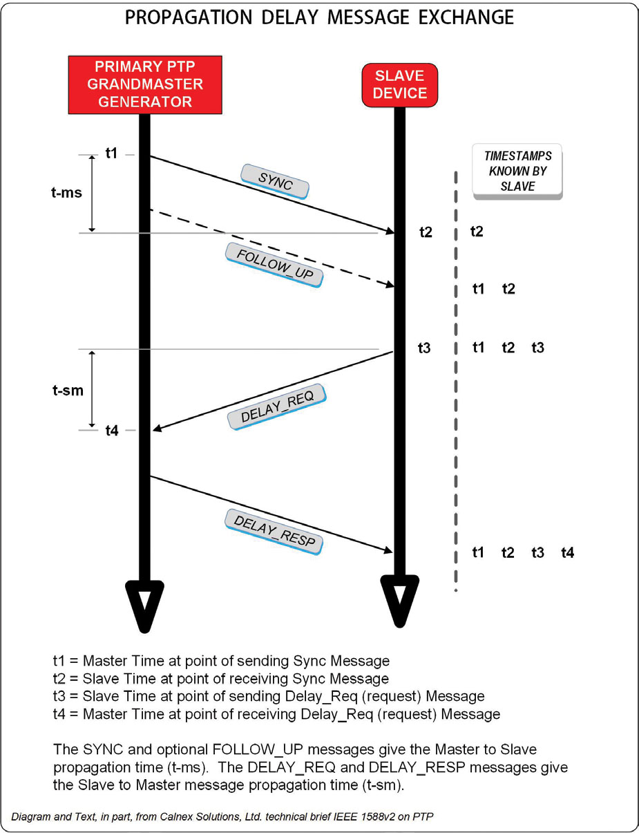
A new timing reference—known as Precision Time Protocol (PTP)—is based upon IEEE 1588:2008 (as PTPv2). PTP replaces the “video black” (and DARS) timing signals typically used in SDI, AES or analog systems. PTP uses a signal messaging system (Fig. 1) that determines, using propagation delay message exchanges, the precise time reference of the master for each slave device in the network. The PTP messages are sent to each network switch where they are passed on to sources (senders) and end-point devices (receivers) for packet timing and alignment. Each packet on a PMN will reference this common PTP signal timing via protocols described in the appropriate IETF RFCs.

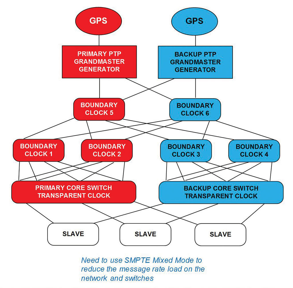
PTP hierarchy consists of a Grand Master (usually with a backup) plus a series of boundary and/or transparent clocks distributed throughout the network (Fig. 2). A “best master clock algorithm” (BMCA) determines “who’s the boss” and “who are its minions”—allow for validation and prioritization in the event of a PTP generator failure.

Proper PTP system design is crucial to the system’s functionality and may vary based upon selected manufacturer’s products or system architectures. For broadcast applications, PTP is specifically refined and described in SMPTE ST 2059-1 and 2059-2. ST 2059-1, which set a point-in-time (i.e., the SMPTE epoch) reference which all devices are clocked from; and ST 2059- 2, describe how PTP works in broadcast centric applications.
PTP coordinates the timing for all audio, video and metadata packets allowing for system synchronization network wide, irrespective of the physical location of the equipment itself. This concept enables LANs to extend throughout a building, across a campus or between geographically separated environments.
PTP changes how devices are referenced on a network versus legacy black burst references in traditional SDI (and analog) video systems. Both PTP and video black reference may be implemented in next-generation facilities and are still quite common, given the hybrid nature (IP+SDI) of system designs.
LINE RATES, BANDWIDTH, FREQUENCIES AND FORMATS
While IP continues to evolve, SDI remains a robust and durable matrix-based X/Y routing and device I/O solution. SDI’s fixed bandwidths (270 Mb, 1.5 Gb, 3 Gb, 6 Gb, 12 Gb) and predictable performance enables isochronous video/audio switching against a reference point as described in SMPTE RP 168. Video router chipsets enable this switching for SD, HD or UHD signals accordingly. Although still quite usable and reliable, SDI employs a “fixed-matrix” that constrains facility growth bound to the fundamental I/O matrix (e.g., matrices of size 32x32 to 1152x1152 or above). Growing beyond a fixed-size SDI-matrix is complicated, expensive and may better warrant a forklift upgrade or the acceptance of a “blocking” architecture.
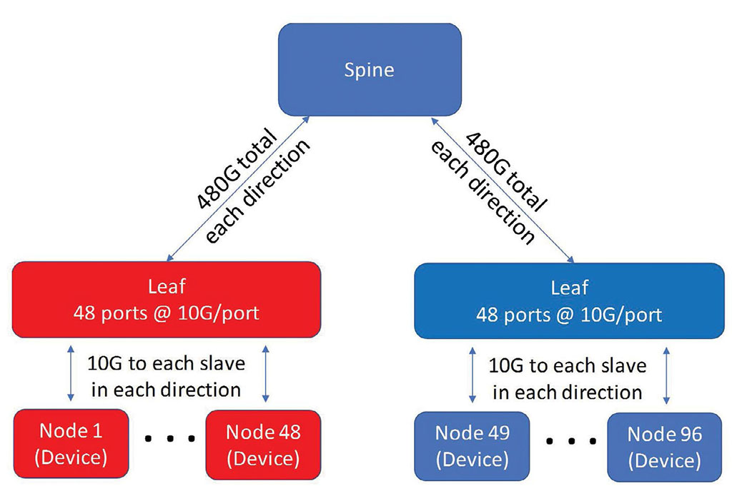
IP eliminates these factors. When designed properly, IP is essentially a non-blocking and unlimited- in-scale architecture. Fixed-matrices, prescribed bandwidths, and SDI constraints are eliminated in IP. With IP, the signal topology is constrained only by the port size and bandwidths on a given Ethernet switch. By employing spine-and-leaf switch architectures (Fig. 3) and sufficient uplink bandwidth from each leaf to each spine, the matrix-limitations of SDI are overcome.

However, this approach poses new challenges to designers; e.g., the initial switch selection must be thoroughly understood, be “PTP-compliant,” and be properly specified as most of the ports on each switch will run “full-tilt” and likely at a constant bit rate at or near the individual port’s bandwidth (i.e., 10G, 25G, 40G, 100G, etc.). Only properly configured media traffic will be permitted— i.e., no email, file-transfers or bursty/uncontrolled or unmanaged traffic should be injected onto this media network.
New systems are best designed to leverage the aggregate capabilities of 100G switches and beyond; utilizing an appropriate port-bandwidth to the signal format transported. For example, a single UHD (4K) signal will consume about 12 GB of data or “bandwidth,” making it impractical to deploy 10G-only ports on the network switches. For UHD using “native IP,” port architectures should be 25G (each)—permitting two UHDTV (2160p) signals per port in each direction.
The good news about IP: it is principally both format agnostic and bandwidth unconstrained (noting that 400G switches are just around the corner). To get more bandwidth, just add more leaf or spine switches. Format wise, running 1080p50 and 720p59.94 or UHD on the same switch is not an issue. If mixtures of 16:9 and 21:9 aspect ratios are anticipated, adding a 4:3 or even a 1:1 aspect signal isn’t a problem provided the sender’s and receiver’s devices accept those capabilities (noting that ST 2110 allows for picture widths and heights up to 32,767 pixels or rows).
IP essentially “future proofs” the broadcast signal transport agenda going forward. However, engineers must also be very aware of the internal architectures of the selected switch vendor’s products—things which must include PTP-compliant and possess the ability to manage the control and data planes through external SDN (software defined networking) principles.
NATIVE IP AND COTS EQUIPMENT
Probably IP’s biggest “promise” is that Common Off-the-Shelf (COTS) components will now do the heavy lifting. By deploying appropriate manufacturer’s switches, SFPs, and fiber optic media for transport and/or using general computing servers equipped with appropriate NICs, the ability to make the system extensible well into the future is achieved. Nonetheless, designers need to be aware of switch (ports) and server (NIC) capabilities when making choices—as many of these new devices may be only “partially-aware” or compliant with the emerging standards and protocols. Some broadcast equipment providers may insist on specific external server or gateway products which must be included to communicate with third party “broadcast controllers” or to manage signal flows when traversing the realm of multicast flows.
As time moves forward, vendor-specific sender/receiver components will move to “native IP” inputs and outputs. SDI may eventually become an option rather than the norm. Cameras, production switchers (vision mixers), audio devices, graphics and playout devices will—or already have—added IP-based interfaces. Instead of multiple BNCs or XLRs, devices will share common SFP-based I/O ports and include backup/secondary ports for resiliency (i.e., for ST 2022-7 or -8 topologies).
With an all-IP system, the need for SDI is reduced or removed entirely—adding flexibility to the system as it more easily expands. When the devices all interoperate properly—achieved, in part, by strict adherence to standards (SMPTE, IETF, etc.), the fundamental architecture of the system can be extended to meet growing demands long into the future.
In the final part of this series, we will explore the changes in cabling, a set of best practices and some human resource guidelines to prepare for the IP-transition.
Karl Paulsen is CTO at Diversified and a SMPTE Fellow. He is a frequent contributor to TV Technology, focusing on emerging technologies and workflows for the industry. Contact Karl atkpaulsen@diversifiedus.com.
Get the TV Tech Newsletter
The professional video industry's #1 source for news, trends and product and tech information. Sign up below.

Karl Paulsen recently retired as a CTO and has regularly contributed to TV Tech on topics related to media, networking, workflow, cloud and systemization for the media and entertainment industry. He is a SMPTE Fellow with more than 50 years of engineering and managerial experience in commercial TV and radio broadcasting. For over 25 years he has written on featured topics in TV Tech magazine—penning the magazine’s “Storage and Media Technologies” and “Cloudspotter’s Journal” columns.
