Does DTV Interference From Taboo Channels Exist?

Charles W. Rhodes
While planning DTV Service circa 1996, the FCC assumed that there would be no interference between a pair of DTV signals on channels which for analog transmission in the UHF band had a “taboo” relationship. That assumption was based on input from the FCC Advisory Committee on Advanced Television Systems.
So far, so good. The commission was able to use formerly taboo channels for DTV and to my knowledge, this has not caused significant interference. This allowed planners to use what had been a taboo channel to relocate broadcasters during the transition from NTSC to DTV.
Let’s assume there was a station transmitting NTSC on Channel 30. Now it is transmitting DTV signals on Channel 30 from that site. Another station in that community may have been allocated Channel 44 or 45 for DTV transmissions. This station’s transmitter might be anywhere in the community. That would be OK for DTV, but would not have been permitted for NTSC because both Channels 44 and 45 have a taboo relationship with Channel 30. Under NTSC rules, NTSC transmitters could not be less than 10 miles apart if they operated on a pair of taboo channels.
With repacking now in the future for many UHF broadcasters, the problems of interference between DTV signals crammed into Channels 14–29 for example, need to be reconsidered. That is why my colleagues and I have carried out laboratory experiments to quantify the robustness of actual DTV receivers to undesired signals on taboo channels.
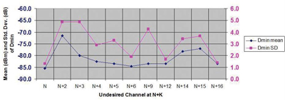
Fig. 1: Dmin with single interferor for 26 converters. The Noise
Limited receiver sensitivity equals–85 dBm in this figure. With
interference, Dmin increases by the mean value (–71 dBm for N+3)
for 50 percent of receivers. For 84 percent of receivers,
Dmin is 4.9 dB higher. Interference on N+3, N+9, N+14
or N+15 may also be significant.
SO WHAT WERE THESE UHF TABOOS?
First, those taboo channel relationships are with respect to the desired channel N. The analog taboos were N+/–2, +/–3, +/–4, +/–5, +/–7, +/–8, and +14 and +15. These last two so-called “image channels” deserve some explanation. All TV receivers employ the superheterodyne principle invented in 1917 by Major Edwin Armstrong, who was trying to detect the ignition noise of enemy airplane engines. Such ignition noise is very faint at the distances at which detection was needed, tens of miles.

Armstrong knew that vacuum tubes could provide gain at low frequencies much better than they could at higher frequencies so he downconverted the ignition noise (RF) to just above audio frequencies. He called his circuit a “superheterodyne,” and that name stuck. In the early 1920s he designed very sensitive radio receivers on this principle. The antenna circuit was tuned to the desired station’s frequency, and this was fed to the frequency conversion device, a vacuum tube called the “mixer.” Each superhet had a local oscillator and that was tuned to a frequency above the desired station by what he called the “intermediate frequency,” typically then 50 kHz. The local oscillator (LO) sine wave overloaded the mixer tube to generate second order distortion products: F osc. + desired frequency; and F osc. – desired frequency.
He then amplified the difference frequency, which was around 50 kHz and detected the amplified IF signal.
However, he quickly discovered that if there were another station 100 kHz above the desired station in frequency, he heard both. He realized that his superhet was equally sensitive to signals above and below the frequency of the LO. He called this spurious (meaning unwanted) response an “image” and that name stuck.
Now consider a DTV station on Channel 30 (N) whose center frequency is 569 MHz. The LO to receive this signal must be tuned to 44 MHz plus 569 MHz to get the difference frequency of 44 MHz which is the intermediate frequency (IF) of TV receivers in North America. Alas, if there is a station on Channel 44 (N+14) centered at 569 MHz + 14* 6 MHz = 653 MHz, or a station on Channel 45 (N+15) whose center frequency is 569 MHz + 15* 6 MHz = 659 MHz, that signal will also be heterodyned to the 6 MHz wide IF band centered at 44 MHz. These signals will all pass thru the IF amplifier to the second detector. Being DTV, undesired signals appear as noise in the output of the IF amplifier. This noise from the image signals adds to the receiver-generated noise and the grand total of all noise must be at least 15.2 dB below the desired signal level or reception fails.
Analog TV tuners typically had one tuned circuit between the antenna and the RF amplifier, and two tuned circuits between the RF amplifier and the mixer. These were tuned to the desired channel and they attenuated signals 14 or 15 channels higher than the desired channel. The FCC established a minimum spacing between analog TV transmitters on channel pairs such as N and N+14/15 so that with the RF selectivity of the tuned circuits in analog TV sets, interference was prevented.
For DTV planning, the FCC believed that no rules were needed to prevent DTV-DTV interference. That is, they believed that DTV receivers would be designed to reject such interference. The FCC rules speak of a desired to undesired signal power ratio (D/U).
Designers of tuners seized upon the notion that the FCC said that DTV-DTV interference was improbable, and designed DTV tuners with little or no RF selectivity. This is why we have run experiments with two and more DTV signals to see what happens with DTV receivers. We tested 26 NTIA-approved DTV converter boxes, (there are about 30 million NTIA-approved converter boxes in American homes providing DTV reception).
We found that these receivers can lock to a desired signal and display pictures down to –85 dBm. The FCC estimated the D/U ratio for DTV-DTV interference to be –63.00 dB, so the maximum undesired signal power could be –85 dBm + 63 dBm = –22 dBm. So we set the U power to –20 dBm and found that with either image channel present, the receivers were being desensitized by about 8 dB—half were below average and the others above average. What it means is that with desensitization by strong undesired signals, people receiving a weak desired signal now may lose reception of that (weak) signal when after repacking, interference is caused by strong undesired signals, especially image signals on N+14 and/or N+15.
Fig. 1 shows our test results. The blue squares represent the loss for 50 percent of the units tested. The magenta squares represent one standard deviation (SD). One standard deviation from the mean 84 percent of the population should have reception.
In Fig. 1, the mean (50 percent) values for N+14 and N+15 are about 8 dB. As one SD equals 3.6 dB, it follows that 68 percent of the people would have reception provided their desired signal is received 12 dB above –85 dBm, statistically speaking.
Significant interference from a single U signal on channels N+/–2 or +/–3 also was found in our tests as is also shown in Fig. 1. More on this in my next column. Stay tuned.
Charles Rhodes is a consultant in the field of television broadcast technologies and planning. He can be reached via e-mail atcwr@bootit.com
Get the TV Tech Newsletter
The professional video industry's #1 source for news, trends and product and tech information. Sign up below.
