How Will IBI Affect DTV Reception After Repacking?

Charles W. Rhodes Last month, we discussed third-order intermodulation (IM3) products seldom covered in the technical literature: 2Fa + Fb, and 2Fb + Fa. We started with spectrum plots for two unmodulated carriers at the center of Ch. 9 (189 MHz) and Ch. 11 (201 MHz). These IM3 products 2*189 + 201 = 579 (MHz) and 2* 201 + 189 = 591 (MHz) fall in the UHF band, but the signals generating them are in the high VHF band. Therefore I call this inter-band interference (IBI).
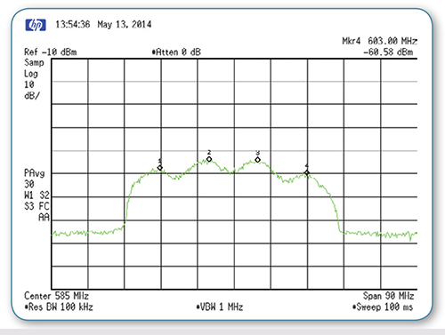
With a pair of Rohde & Schwarz DTV signal generators, I set one to generate an ATSC signal on Ch. 9, and the other on Ch. 11. Fig. 1 shows the spectrum, which was not expected to look like this at all. Marker #2 (579.0 MHz) and Marker #3 (591.0 MHz) are at the IM3 center frequencies. But what were the frequencies of Markers #1 and #4?

Fig. 1: Spectrum plot of third-order distortion products generated by two ATSC signals on Chs. 9 and 11—Mkr #1: center frequency third-harmonic center frequency Ch. 9; Mkr #2: IM3 Chs. 9 and 11; Mkr #3: the other IM3 of Chs. 9 and 11 center frequencies; Mkr #4: center frequency of the third harmonic of Ch. 11. I soon found that Marker #1 (567.0 MHz) is the third harmonic of Fa (189 MHz) and Marker #4 (603 MHz) is the third harmonic of Fb (201 MHz). These third harmonics are about 6 dB lower in power than the IM3 products and they are real.
The third harmonic of Fa falls within UHF Channel 30 while the third harmonic of Fb falls in Channel 36. These being third-order distortion products of signals nominally 6 MHz wide are nominally 18 MHz (three channels wide). So the noise power spectrum of Fig. 1 extends from Channel 29 up to Channel 37.
Amazing, but the third-order distortion products of two high VHF band undesired (U) ATSC signals can cause interference to Channels 29–37.
THIRD HARMONICS
But, what about the other third-order distortion products 2Fa – Fb and 2Fb – Fa? Those intermodulation products fall in Channels 7 and 13 respectively. 2*189 – 201 = 177 MHz. (Channel 7) and 2*201 – 189 = 213 MHz. (Channel 13).
While the IM3 products are somewhat larger than the third harmonics as shown in Fig. 1, these harmonics should not be ignored. We must also keep in mind that IM3 products cover three contiguous channels.
Higher than third-order distortion products exist, but in general, their power is much smaller than the lower-order distortion products (second and third order). Therefore they are not usually significant. The IM3 products generated by DTV signals on Chs. 9 and 11 are 2*189 + 201 MHz = 579 MHz and 2*210 + 189 MHz = 591 MHz. These distortion products fall in the UHF band, but they are not centered in UHF channels.
For example, the center frequency of channel 30 = 569 MHz, while the new IM3 product is centered at 567 MHz. This is true for all of these third-order distortion products of two or more high VHF band signals; their center frequencies are 2 MHz below the center of the UHF channel.
In addition to IM3, we also have triple beats (TB) of the form Fa + Fb +Fc. Where Fa, Fb and Fc are in the high VHF band, these TBs fall in the UHF Band. The center frequency of the lowest TB of the high-band VHF signals (Channels 7 + 8 + 9) is equal to 549 MHz. The highest TB (channel 11,+12+13) falls at 621 MHz. These center frequencies are in Chss 26 and 39 respectively, but their spectrum starts a 549 – 9 = 540 MHz signal that corrupts Ch. 25. The spectrum ends at 621 + 9 = 640 MHz, corrupting Ch. 40. A TB is a more potent source of interference than is an IM3 which is also generated by the same pair of these signals.
DTV RECEPTION AFTER REPACKING

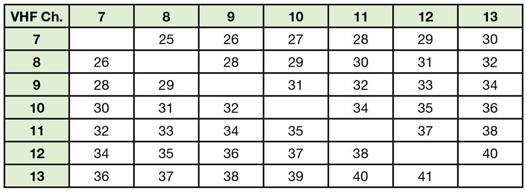
Table 1: VHF triple beats per UHF channel

Table 2: Third-harmonics of center frequencies of high VHF channels

Table 3: UHF channels subject to interference by high VHF band signals I know of no site where all seven high VHF signals can, at the present, be received at about the same power. But consider that one community has Chss 8, 10 and 12 and another community may have the rest, 7, 9, 11 and 13. Between these communities, reception of all seven DTV signals may be possible.
After repacking, I expect that some communities may be allocated five or six or even all seven high-band VHF channels. Why not? The crowding of what will remain of the UHF band will spill over into an already-crowded high VHF band. When—and not if—this happens, I expect IBI on a significant scale. Some of the TBs from the high VHF band will fall in former UHF channels so cellphones using the new 600 MHz band will have to be designed with enough RF selectivity and/or wide enough linear dynamic range to avoid IBI.
My colleague Stanley Knight, came up with Table 1, which shows the distribution of TBs in the UHF band. The center frequencies of the third harmonics of high-band VHF signals are given in Table 2, which also identifies the UHF channel within which these center frequencies fall. Those UHF channels subject to IBI from two high VHF band signals is shown in Table 3.
There is more to IBI that will be covered in my next column. Stay tuned.
Charles Rhodes is a consultant in the field of television broadcast technologies and planning. He can be reached via e-mail atcwr@bootit.com.
Get the TV Tech Newsletter
The professional video industry's #1 source for news, trends and product and tech information. Sign up below.
