Illuminating ‘Illuminance’ Part 2

In part 1 of this subject, you were introduced to the basic terms and definitions for lighting calculations. It was suggested that you refer to them by their units rather than the confusing academic names. Lamps convert electrical energy to lighting energy, which is expressed in lumens. The efficiency of this conversion of electrical energy to light energy is expressed by the ratio of lumens per watt.
We then introduced “illuminance,” the incident light falling upon a surface. This can easily be measured by our light meter. The quantity measured is in units of “foot-candles” (in our “imperial” system) or “lux” in the metric system. (Note: 10.76 lux equals 1 foot-candle). The average foot-candles falling on a surface is defined by dividing the total lumens falling on the surface by the area of the surface in square feet.
The actual distribution of this energy within a three-dimensional space is usually provided by the fixture manufacturer by documenting many values of “candlepower” (luminous intensity) for all useful directions.
By definition, we can calculate the incident light falling on an individual location on a plane by utilizing the “square law” relationship: foot-candles are equal to the candlepower divided by the square of the distance from source to plane. If the plane is not perpendicular to the direction of the candlepower, we must modify the incident light by multiplying by the cosine of the tilt angle of the plane. We now have two formulas.
The first provides a means to estimate the average incident light on a surface. The more useful second formula provides a more accurate means of determining the incident light at a specific location. It is the one that we will use.

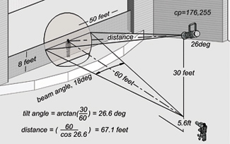
Fig. 1: Diagram of example Measuring incident light is the usual means of determining exposure because of its simplicity. The meter is pointed at the camera. If it is an exposure meter, it gives the values of camera settings as calculated by the simple formula that relates film speed, shutter speed and lens iris. An average reflectance of 18 percent is assumed. Electronic camera’s sensitivity is generally given as foot-candles or lux required at a specific aperture, for example, 250 foot-candles at f8.0.
AN EXAMPLE
Assume that we wish to evenly light an area that is 8 feet high and 50 feet wide. In this example, (see Fig. 1) this area is a vertical plane, located at the fire curtain line in a theater, a good place to focus a full-stage front wash. I have decided to use 26 degree ellipsoidal spots using 750 W lamps located in a cove located 50 feet from stage at 35 feet 6 inches above the stage level.
At this point let me introduce another lighting property created to help us, “Beam Angle.” Beam angle is defined as the edges of the light beam where the candle power is one-half of the candlepower at the center of the beam. The beam is focused on a flat plane (which, of course, is true in our example).

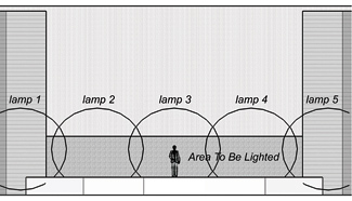
Fig. 2: Front view, lamp beam placement Why one-half? This provides a realistic way to quickly accommodate the unevenness in value of the candlepower within the beam of the lamp. The idea is that if we have a number of lamps that we wish to cover an area, as in our case, we need only place the lamps so that the edge of each lamp’s beam angle is adjacent to the 50 percent edge of its partner on each side. It assumes that the light outside of the beam angle (the “field angle”) will add together to achieve a flat output. The remarkable thing is that it actually works!
Referring to the diagram, you will see the layout of our example with the values of the relevant data. Notice that I am using the eye level of the subject at 5 feet 6 inches above stage level as the measurement as well as the lamp focus point. The tilt angle of 26.6 degrees (height to distance of 0.5) was chosen because I consider it to be the maximum tilt angle for a main light.
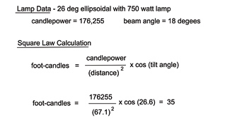
You should be aware that the common theatrical 45 degree tilt angle is just too unkind to a performer on camera. Simple trigonometry is used to calculate the actual distance from the lamp to subject. From this we calculate the incident light at the center of the beam using the square law formula taking into account the tilt angle (see Fig. 3). Our calculation yields 35 foot-candles.
I should point out that this value represents what would be obtained in a perfect world. The one factor that has the most influence other than the condition and adjustment of the fixture is the actual voltage present at the lamp. Because of this subject’s importance, I intend to cover it in depth in a future column. For now, let us assume that everything is ideal.

Fig 3: Center beam foot-candle calculation Next, the beam angle cone of each lamp is copied right and left with a slight overlap until the desired area is covered beyond the offstage limits. The number of fixtures turns out to be five (see Fig. 2). Note that three will just not make it. Remember that the beam edge is one-half the intensity.
An interesting result is that it is obviously possible to use only four fixtures and cover the area. The overlay would be at the center of the stage and would have to be very smooth by means of de-focusing and diffusion. In actuality this could be difficult to obtain using an ellipsoidal fixture. Considering the importance of the center stage position, it is not recommended.
Again, it is important that the beams of the end lamps extend beyond the edge of the focus area because the maximum candlepower is only at the center. Be advised that all long throw fixture types exhibit this unevenness to some degree.
If you intend to do this type of analysis often, consider making templates from manila paper stock for the beam angles for fixtures that you intend to use. You will still have to calculate the lamp-to-subject distance in a section view unless the tilt angle is a constant, not usually the case.
For experienced AutoCAD users, you could devise a simple Lisp or Visual Basic routine to solve the square law equation and then automatically draw the beam angle lighted area for each fixture.
For those who want to investigate more sophisticated solutions there are lighting calculation programs available for a very reasonable investment. Be forewarned that the learning curve can be intimidating.
Bill Klages would like to extend an invitation to all the lighting people out there to give him your thoughts atbill-klages@roadrunner.com.
Get the TV Tech Newsletter
The professional video industry's #1 source for news, trends and product and tech information. Sign up below.
