LDM—Stacking Signals for Improved Performance

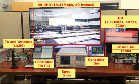
LDM prototype hardware and demo configuration. Mobile/Indoor: 2.6 Mbps 720p SNR=-0.4dB, High data rate: 20 Mbps 4KUHD SNR=18.5 dB (Courtesy ETRI) Today, TV broadcasters need to deliver content to devices ranging from smartphones and tablets to huge LCD screens. Successful reception of today’s over-the-air ATSC DTV transmissions requires a real world signal-to-noise ratio in the range of 20 dB. Multipath (echoes) have to be within the range of the TV’s adaptive equalizer and stable enough for the adaptive equalizer to track them. The system works well with outdoor antennas, not as well with indoor antennas and not at all for mobile reception, unless ATSC-MH is used.
One of the priorities for ATSC 3.0 is to provide reception to this wide range of devices within the same bandwidth used for today’s ATSC signals. One way to accomplish this is to send two streams—one robust low data rate stream containing the core content and a less robust, higher data rate stream providing enhanced content—at higher resolution, greater dynamic range and expanded color gamut.
TDM, FDM OR LDM?
DVB-T2 allows multiple physical layer pipes (PLP) and these can be configured with different carrier modulation, number of carriers (FFT size) and coding. By using two or more PLPs it is possible to transmit data streams with different levels of robustness. Multiple data streams can be created by sending the streams at different times (Time Division Multiplex or TDM) or by allocating specific OFDM carriers to different streams (Frequency Division Multiplex or FDM).
Communications Research Centre Canada (CRC), Electronics and Telecommunications Research Institute (ETRI), Korea and Euskal Herriko Unibertsitatea (EHU), Spain have developed another way to transmit two (or more) data streams in one channel—Layered Division Multiplexing or LDM. Use of LDM does not preclude use of TDM or FDM. TDM or FDM can be applied to layers in LDM. LDM can be applied to an individual TDM PLP if desired, although this removes one of the benefits of the LDM spectrum overlay technology—its ability to use 100 percent of the channel 100 percent of the time for robust and less robust layers.
This month I’ll provide a quick overview of LDM and the results of the first tests of LDM hardware.
LDM consists of an ultra-robust upper layer (typically QPSK modulation) and a less robust higher data rate lower layer, typically using a higher order, more complex constellation transmitted in the same spectrum. The amount of power devoted to the upper and lower layer constellations is adjustable. More of the transmit power can be assigned to mobile/indoor/distant service than for fixed service reception closer to the transmitter or with outdoor antennas.

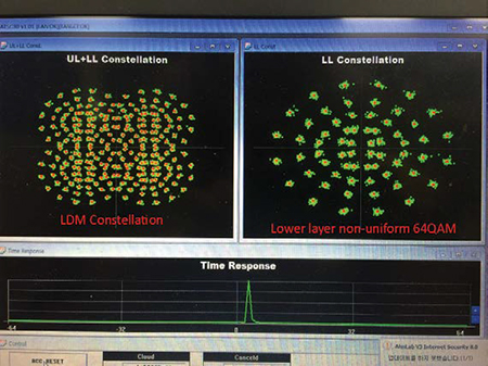
Fig. 1: LDM constellation on the prototype hardware (Courtesy ETRI) The lower layer signal can be received by decoding the upper layer and canceling the upper layer from the received signal. A 2014 IBC presentation from Communications Research Centre Canada compared LDM to a double-decker bus that carries more people in the same amount of space. Fig. 1 shows the combined LDM layer’s constellation on the left and the lower layer’s constellation after the upper layer is canceled on the right.
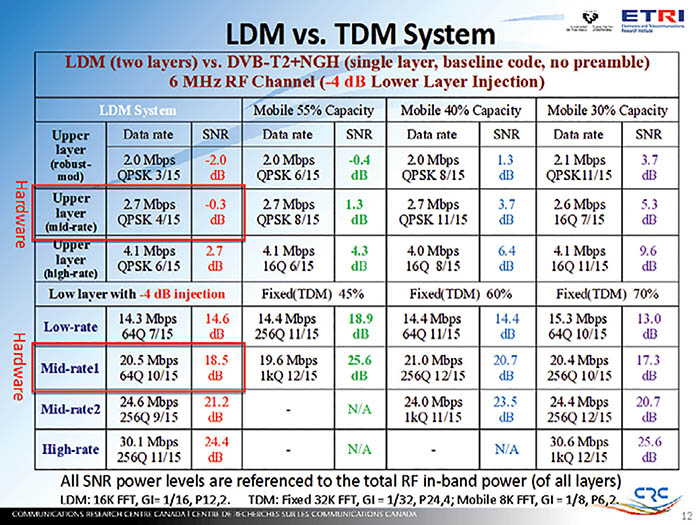
Why use LDM when TDM, already implemented in DVB-T2 and NGH, allows for more than one layer or robustness? Fig. 2 compares the performance of a two-layer LDM system with –4 dB lower layer injection with a DVBT2+ NGH single layer system using 55 percent, 40 percent and 30 percent of the DVB-T2 channel capacity for the more robust “mobile” stream. (The table also is available at www.transmitter.com/RF251/LDM.pdf).
LDM PERFORMANCE
As you can see, TDM cannot match LDM’s upper layer robust SNR of –0.3 dB even with 55 percent of the TDM channel capacity devoted to mobile. With this capacity allocation, TDM’s higher data rate (19.6 Mbps) stream is 0.9 Mbps less than LDM and the SNR is over 7 dB worse! Dropping the TDM mobile allocation to 40 percent allows the higher data rate stream to increase to 21 Mbps (0.5 Mbps more than LDM) and reduces the required SNR to 20.7 dB, 2.2 dB worse than with LDM. However, the lower data rate robust TDM stream now needs an SNR of 3.7 dB, 4 dB worse than LDM!
LDM can be configured to provide a robust upper layer data rate of 4.1 Mbps at 2.7 dB SNR while still allowing a less robust data rate of 30.1 Mbps in the lower layer at an SNR of 24.4 dB. These data rates should be more than sufficient to allow robust transmission of HD content with multichannel audio in the upper layer and a high-quality UHDTV, and with even more channels of audio in the lower layer.
One benefit of LDM is that the robust upper layer signal is available whenever the lower layer signal is being received. It provides more robust synchronization and channel characterization, allowing faster recovery if the lower layer signal briefly drops below threshold and, of course, it provides a fall-back signal when the lower layer signal isn’t available.
Another benefit is that, if at some point in the future a new modulation or coding method arrives, we want to deploy it without breaking existing sets. The lower layer could be changed to the new method, but as long as the upper layer signal remains, the existing sets could receive it. The older sets would lose the higher data rate services, but still receive a quality picture until the consumer decided to purchase a set capable of receiving the new lower layer.

Fig. 3: LDM prototype hardware and demo configuration Does LDM actually work? Is it practical? I had a chance to see it demonstrated in Washington D.C. using hardware developed at CRC and the Electronics and Telecommunications Research Institute (ETRI). Fig. 3 shows the setup.
This system was transmitting two separate programs, 4K-UHD at 19.43 Mbps, 60 fps and HD at 720p, 60 fps at very low power to a receiver and antenna on the other side of the table. The system was very robust; it was difficult to break up the 4K stream; and I found it impossible to break the HD stream.
Even though this was first-generation FPGA-based hardware, the implementation loss was low with this setup using a –4 dB injection level. Hardware upper layer performance was no more than 0.2 dB worse than simulation for AWGN, Ricean, Rayleigh and 0.0-dB echo channels. The worst case lower layer performance loss in the hardware implementation was 0.7 dB in a Rayleigh channel. Hardware upper layer performance will improve as synchronization is improved. Lower layer performance will improve with better cancellation of the upper layer signal.
LDM BENEFITS
The benefits of LDM should outweigh the added complexity and cost on the receiver side. CRC and ETRI says the increase in receiver complexity for LDM is less than 10 percent. In exchange for that, it provides an SNR gain of 4–6 dB or more. It operates independently to MIMO, MISO, PLP, TI (Time Interleaver), pilots, GI (guard interval), preamble and peak-to-average power reduction schemes, making it compatible with most, if not all, ATSC 3.0 physical layer proposals.
For a detailed technical study of LDM, visit http://ieeexplore.ieee.org/xpl/articleDetails.jsp?arnumber=6746098 to download “Cloud Transmission: System Performance and Application Scenarios” by Jon Montalbán, from the Dept. of Communications Engineering at the University of the Basque Country, and Liang Zhang, Unai Gil, Yiyan Wu, Itziar Angulo, Khalil Salehian, Sung-Ik Park, Bo Rong, Wei Li, Heung Mook Kim, Pablo Angueira, and Manuel Vélez. The article was published in June 2014. Work on LDM is continuing so the results in that article may not match those in the data Yiyan Wu at CRC provided me in January 2015 for use in this article.
Comments are welcome! E-mail me atdlung@transmitter.com.
Get the TV Tech Newsletter
The professional video industry's #1 source for news, trends and product and tech information. Sign up below.

Doug Lung is one of America's foremost authorities on broadcast RF technology. As vice president of Broadcast Technology for NBCUniversal Local, H. Douglas Lung leads NBC and Telemundo-owned stations’ RF and transmission affairs, including microwave, radars, satellite uplinks, and FCC technical filings. Beginning his career in 1976 at KSCI in Los Angeles, Lung has nearly 50 years of experience in broadcast television engineering. Beginning in 1985, he led the engineering department for what was to become the Telemundo network and station group, assisting in the design, construction and installation of the company’s broadcast and cable facilities. Other projects include work on the launch of Hawaii’s first UHF TV station, the rollout and testing of the ATSC mobile-handheld standard, and software development related to the incentive auction TV spectrum repack. A longtime columnist for TV Technology, Doug is also a regular contributor to IEEE Broadcast Technology. He is the recipient of the 2023 NAB Television Engineering Award. He also received a Tech Leadership Award from TV Tech publisher Future plc in 2021 and is a member of the IEEE Broadcast Technology Society and the Society of Broadcast Engineers.
