Next-Generation Error Correction Codes

DOUG LUNG
Last month I showed how coding and error correction allows next-generation broadcast technologies such as DVB-T2 and DVB-NGH to achieve performance very close to the Shannon limit. This month I’ll use a very simple matrix to highlight the features of low density parity-check codes. This is not a tutorial, but an example that I hope will trigger your interest in codes. For a more in-depth discussion of LDPC codes, Google Bernhard M.J. Leiner’s “LDPC Codes–a Brief Tutorial,” and Sarah J. Johnson’s “Introducing Low Density Parity-Check Codes.” These papers provide the mathematical background I’m skipping here.
PARITY CHECK MATRIX
Error correction works by adding extra bits that can be used to recover bits that are lost or corrupted during reception. You may remember in the days before Ethernet when we sent ASCII data over a serial connection or modem, a parity bit was often added so the sum of the bits was always odd (1) or even (0). Of course, it was prone to error because if two bits were flipped the parity could be correct even if the received data was wrong.
To get around that problem, advanced coding systems use a parity check matrix. Fig. 1 shows a parity check matrix for an 8,4 linear block code.
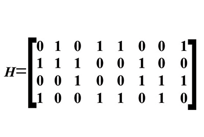
Fig. 1: Parity check matrix for an 8,4 linear block code.
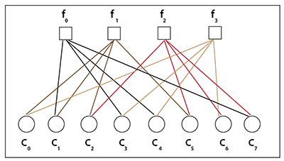
Fig. 2: Same parity check matrix shown as a Tanner graph. Each row is a parity check equation and generates an output based on a bit by bit comparison of the codeword. The parity of the transmitted codeword is such that when applied to the matrix, the result of equation will be even (0). If the received codeword is correct, the result will also be zero. Take a piece of paper and compare the codeword 00011000 with the parity check matrix. You will find each equation provides an even result (0). However, the power of the method becomes evident when one bit is corrupted.
While it may not be obvious looking at the parity check matrix, each bit of the codeword is “connected” to two parity check formulas. The matrix can also be shown as a Tanner graph (Fig. 2). In this diagram, the variable nodes are at the top (f0, f1, f2, f3). The check nodes are at the bottom (c0...c7). Our parity check matrix H defines the connections between the variable nodes and the check nodes. You can find out more about Tanner graphs in Leiner’s and Johnson’s papers.
One value of these connections is they allow error recovery. If the 00011000 codeword was received as 00011001, the result of the parity check matrix equation would be 1010 instead of 0000. If the received codeword was 10011000, the equation result would be 0101. Take a look at Fig. 1 and you’ll see how this allows us to determine which bit was in error and correct it.
The example shown here doesn’t really qualify as a LDPC code because there are far too many “1’s” in it, but it shows how the process works.
CREATING COMPLEX CODES
While it is very simple, it provides the basis for a thought experiment we can do that shows how larger, more complex codes are created.
Imagine what will happen if we increase the size of the parity check matrix to the point that “soft” decisions are possible— the results of many equations, covering a large amount of data, are combined to determine which codeword is most likely to be correct. Once a bit is determined to be correct, it can be used to help correct other bits in an iterative process. This is how LPDC codes are able to approach the Shannon limit in performance.
The example here would be a “regular” code because all of the check nodes have an equal number of connections. More advanced LDPC codes can be “irregular” with a different number of connections at each node. For communications links, the LDPC codes can be spread over multiple carriers and over time to increase robustness. Generating LDPC codes that approach the Shannon limit is possible, but as the matrix size grows it becomes more difficult to encode and decode the data. One problem with LDPC codes is that with a smaller matrix size, a few bad bits will slip through.
Rather than deal with these random errors by increasing the size of the LDPC code or increasing the number of iterations when decoding it, the DVB-S2 and DVB-T2 standards concatenate BCH coding to clean up these bad bits. A BCH code is a multilevel cyclic variable length code. It has algebraic structures designed for efficient error correction making it ideal for use in low power devices.
BCH codes were invented by Hocquenghem in 1959 and Bose and Ray-Chaudhuri in 1960. The website http://cwww.ee.nctu.edu.tw has a good explanation of BCH codes if you can follow the math.
Nick Wells explains how LDPC and BCH work together to allow DVB-T2 to perform within 0.6 dB of the Shannon limit in his presentation “DVB-T2 in relation to the DVB-x2 Family of Standards” available at www.atsc.org. The DVB-T2 FEC frame consists of 64,800 bits, including BCH forward error correction bits and LDPC check bits. The BCH FEC bits add very little overhead.
While it isn’t easy to work through the formulas that define how advanced coding methods work, I hope this introduction gives you an understanding of their role in modern communications as well as an appreciation of how this field is still evolving. Much of the performance improvement from DVB-S to DVB-S2 satellite transmission can be credited to more advanced coding methods.
To learn more, a good place to start is David MacKay’s “Information Theory, Inference, and Learning Algorithms” at http://www.inference.phy.cam.ac.uk.
MacKay also has a web page showing a graphic example (using a Dilbert cartoon!) of Iterative Probabilistic Decoding of a Low Density Parity Check Code.
I’m still learning about these advanced coding methods work and hope to be able to write more about them in future columns.
Comments and questions are welcome! Email me at dlung@transmitter.com.
Get the TV Tech Newsletter
The professional video industry's #1 source for news, trends and product and tech information. Sign up below.
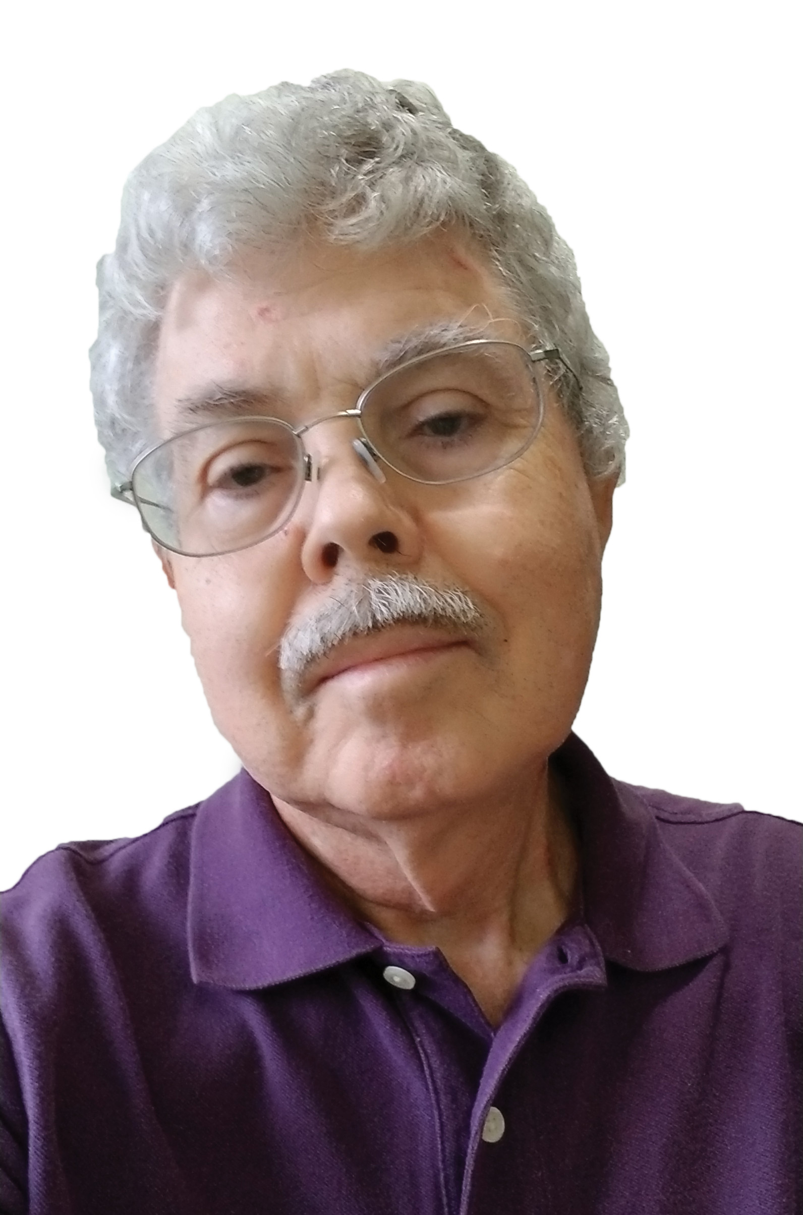
Doug Lung is one of America's foremost authorities on broadcast RF technology. As vice president of Broadcast Technology for NBCUniversal Local, H. Douglas Lung leads NBC and Telemundo-owned stations’ RF and transmission affairs, including microwave, radars, satellite uplinks, and FCC technical filings. Beginning his career in 1976 at KSCI in Los Angeles, Lung has nearly 50 years of experience in broadcast television engineering. Beginning in 1985, he led the engineering department for what was to become the Telemundo network and station group, assisting in the design, construction and installation of the company’s broadcast and cable facilities. Other projects include work on the launch of Hawaii’s first UHF TV station, the rollout and testing of the ATSC mobile-handheld standard, and software development related to the incentive auction TV spectrum repack. A longtime columnist for TV Technology, Doug is also a regular contributor to IEEE Broadcast Technology. He is the recipient of the 2023 NAB Television Engineering Award. He also received a Tech Leadership Award from TV Tech publisher Future plc in 2021 and is a member of the IEEE Broadcast Technology Society and the Society of Broadcast Engineers.
