Recalculating DTV Coverage

Doug Lung
Back in the days of analog TV, the Grade B contour map was the measure of a station’s coverage. It was plotted using a set of curves developed with a combination of field measurements and free space path loss based on the station’s channel height above average terrain for the radial studied and effective radiated power on that radial.
The set of curves for the predicted threshold (example: 64 dBμV/m for UHF Grade B), for 50 percent of the locations 50 percent of the time was used for determining coverage, and another set, based on 50 percent of the locations 10 percent of the time, was used to determine the interference contour.
The coverage contour for ATSC DTV used a combination of these two curves (or their mathematical equivalent), to determine the DTV service area contour based on a predicted threshold (example: 41 dBμV/m for a UHF station on Channel 36) at 50 percent of the locations 90 percent of the time.
Field measurements show the FCC curves are fairly accurate for most station locations—the central valley area between Fresno and Sacramento, Calif., being one noted exception—but they didn’t account for terrain beyond 16 km (about 10 miles) from the transmitter site.

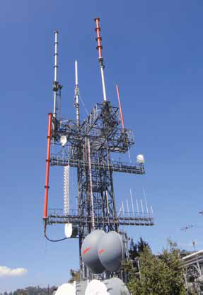
Mt. Harvard antenna tower in Southern California
They also didn’t predict reception at any given location inside the coverage contour. As a result, when the FCC was looking to provide every analog station with a channel for DTV, they used the Longley-Rice Irregular Terrain Model to calculate station coverage at cells inside the contour.
Since the early days of TV, coverage has been based on the use of an outdoor antenna 30 feet above ground. While outdoor antennas are still used today, particularly in rural areas, reception on indoor antennas has become popular.
Since the DTV transition we’ve seen several companies join established firms such as Winegard and Antennas Direct in offering indoor antennas for over-the-air reception—the Mohu Leaf and Walltenna antennas are two examples.
Coverage studies based on signal strengths for outdoor antennas at 30 feet aren’t much help with these antennas.
PICKING APPROPRIATE SIGNAL LEVELS
What level is appropriate for indoor reception? In “DTV in the House, Part 1” (RF Technology, Sept. 5, 2007), I showed a field strength of 67 dBμV/m would be needed at UHF Channel 36. For my coverage studies, I’ve been using 68 dBμV/m (20 dB above the nominal community grade signal level) for UHF indoor reception.
Strong signal coverage is becoming more important as people eschew outdoor antennas in favor of small indoor antennas. In addition to the nominal FCC UHF field strengths of 41 and 48 dBμV/m, I also look at the population predicted to receive a signal at 68, 88 and even 98 dBμV/m.
Increased field strength increases the chance of reception. Remember those FCC curves? For DTV they are based on 50 percent of the locations, 90 percent of the time. In a controversial filing regarding an FCC Notice of Inquiry on the Technical Standards for Determining Eligibility for Satellite- Delivered Network Signals Pursuant to the Satellite Home Viewer Extension and Reauthorization Act of 2004, Hammett and Edison, on behalf of EchoStar, showed a 17.5 dB increase in UHF DTV signal strength was necessary to change the reliability statistic from 90 percent of the time to 99 percent of the time.
A you can see, there is a big difference in the signal level required for reception if a viewer is willing to take some effort, which could include installing an outside antenna or simply wants to plug in one of the new, flat, wall-mounted indoor antennas and call it a day. When designing transmission systems, it is important to take this into account.
For most markets, the transmitter site is already defined, so the key considerations are antenna pattern and transmitter power. The ideal solution to providing the maximum signal to the most number of people would be to use an isotropic (equal power in all directions) radiator or at least one that had equal power at all angles below the radio horizon.
Obviously this isn’t practical. Using an omnidirectional antenna with low elevation gain and a lot of null fill may be practical and will achieve similar results, but due to transmitter and transmission-line power limitations it may be difficult to achieve any significant amount of elliptical polarization, which is also important for reaching indoor antennas.
In the end, the final solution is likely to involve some compromise— a more directional antenna and, if the site height above average terrain allows, use of mechanical beam tilt to put the strong signal where it reaches the most people.
USING ‘WEIGHTED’ POPULATION COUNTS
One way to determine the best combination of azimuth pattern, elevation pattern and mechanical beam tilt is to use a “weighted” population count to compare the alternatives.
First, calculate the population covered at each of the desired signal levels (example: 48, 68, 88 98 dBμV/m) for an isotropic antenna. Give each signal level a weight— for example, 0.1, 0.5, 0.3 and 0.1 for 48, 68, 88 and 98 dBμV/m, respectively.
Multiply the population receiving each signal level by the weight and sum the results; this is your reference. Do the same for each antenna pattern, seeing how close, on a percentage basis, each one comes to isotropic antenna.
Comparing a large number of antenna variations will take a long time. I’ve come up with a way to convert the output of the SPLAT propagation analysis program into a Python NumPy matrix instead of the flat text files I previously used. By putting the elevation and azimuth angles to the receive point or obstruction and path loss from SPLAT in a matrix and combining this with a matrix containing antenna pattern data, I should be able to easily generate field-strength matrices for many different pattern orientations.
Once I figure out how to combine these results with gridded population data, it will provide the population coverage needed to determine the optimum antenna orientation. Look for more on this in a future column.
Comments and questions are welcome. Email me atdlung@transmitter.com.
Get the TV Tech Newsletter
The professional video industry's #1 source for news, trends and product and tech information. Sign up below.

Doug Lung is one of America's foremost authorities on broadcast RF technology. As vice president of Broadcast Technology for NBCUniversal Local, H. Douglas Lung leads NBC and Telemundo-owned stations’ RF and transmission affairs, including microwave, radars, satellite uplinks, and FCC technical filings. Beginning his career in 1976 at KSCI in Los Angeles, Lung has nearly 50 years of experience in broadcast television engineering. Beginning in 1985, he led the engineering department for what was to become the Telemundo network and station group, assisting in the design, construction and installation of the company’s broadcast and cable facilities. Other projects include work on the launch of Hawaii’s first UHF TV station, the rollout and testing of the ATSC mobile-handheld standard, and software development related to the incentive auction TV spectrum repack. A longtime columnist for TV Technology, Doug is also a regular contributor to IEEE Broadcast Technology. He is the recipient of the 2023 NAB Television Engineering Award. He also received a Tech Leadership Award from TV Tech publisher Future plc in 2021 and is a member of the IEEE Broadcast Technology Society and the Society of Broadcast Engineers.
