Seeing Ghosts on a Single Frequency Network
Ghosts of DTV signals could easily be seen on analog TV screens, but with DTV, they are invisible on the TV screen. DTV ghosts, also known as echoes, can only be seen on the screen of a spectrum analyzer.
TO ILLUSTRATE
Fig. 1 shows a single ghost or echo delayed by 1.0 µs. The spectrum analyzer is tuned to channel 37 whose center frequency is 611.000 MHz. Channel 37 begins at 608 MHz, ending at 614 MHz. The instrument's span is 10 MHz.
The interaction of the signal spectrum and that of its ghost produces broad peaks, one for each 1.0 MHz, and between these are deep and sharply defined minima. Ghosts, in the case of single frequency networks (SFN) are the weaker signalssreceived from the multiple transmitters of the SFN while the signal received with the greatest received power is the received signal.
In Fig. 1, I have shown one echo for clarity. Multiple echoes are much more complicated so let's leave them out of this story. The echo in Fig. 1 is only 0.5 dB weaker than the signal.
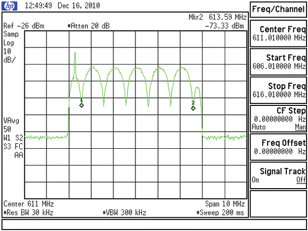
Fig. 1: Typical spectrum analyzer display of an ATSC signal with a 1 μs echo. Marker #1 at 608.59 MH z. Marker #2 = 613.59 MH z. Frequency difference = 5.000 MH z/number of cycles between markers (5) = 1 MH z/ cycle indicates a 1.000 μs echo.
Some of you have tried to see DTV ghosts and failed. Perhaps you tried a 10 µs single echo and got the spectrum like that in Fig. 2.
Where is that ghost? A 1.0 µs echo produces minima every 1.0 MHz, as shown in Fig. 1, so a 10 µs echo would produce a minima every 100 kHz. But you can't see them in Fig. 2.
If we reduce the instrument's span from 10 MHz to say 500 kHz, and make sure that its resolution bandwidth and video bandwidths are significantly reduced and set the sweep speed to 2 seconds (this is most important), you will see the interaction of a 10 µs echo and the signal as in Fig. 3.
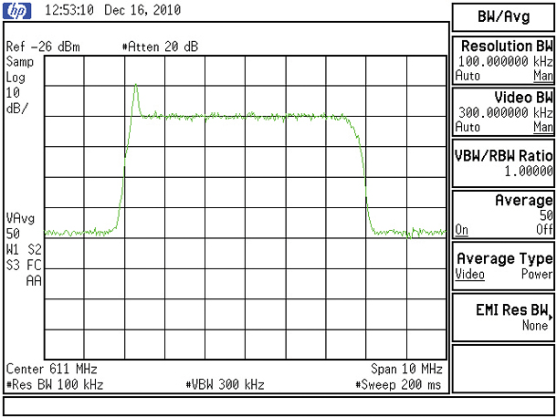
Fig. 2: Spectrum analyzer display of an ATSC signal with a strong 10 μs echo with conventional resolution bandwidth, span and sweep time. The echo is not discernible.
This is how I measure echo delay in my laboratory. If you are careful, you can measure echo delays beyond +/–50 µs by this simple, but tricky, technique. Use Fig. 3 as your model for setting up your spectrum analyzer.
With my Rohde & Schwarz SFE DTV Signal Generator, many echoes are available, each quantified as to delay in microseconds; amplitude relative the signal power in dB; and its phase relative to the signal power in degrees.
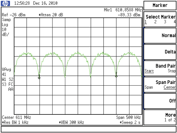
Fig. 3: Spectrum analyzer display of an ATSC signal with a strong 10 μs echo made clearly discernible by reducing resolution bandwidth and span while increasing sweep time as shown. Marker #1 = 610.860 MH z. Marker #2 = 611.160 MH z frequency difference = 0.300 MH z/3 cycles between markers = 0.100 MH z, which indicates 10.000 μs echo frequency. This technique can be used to measure much longer echo delays.
Phase is specified for a signal frequency at the center of the screen. The importance of the phase relationship signal-to-echo is just as important as the signal-to-echo delay (in microseconds), but far less well understood. My spectrum analyzer can be set up for any phase (zero–360 degrees) at whatever frequency is at the center of the screen.
NOW FOR THE TEST
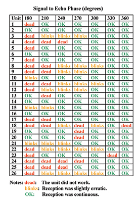
Table I: Test Results with 26 NTIA -approved DTV "converter boxes" Where is this ghost story leading to? My colleagues and I wanted to understand how the phase of an echo at the pilot carrier frequency of the ATSC signal might affect whether or not it can be received. It does adversely affect reception.
We set the center frequency to 611.000 MHz, the Span to 500 kHz, the resolution bandwidth to 1 kHz and the sweep time to 2 seconds to "capture the ghost." This capture is shown in Fig. 3.
What we found for a +10.0 µs echo 0.5 dB below the signal is that the pilot carrier power varied with the phase of this echo, down –25 dB for 180-degree phase relationship, or up +3 dB for 0 dB phasing. It is the difference between path lengths of the signal and its echo that determines the echo delay. A 10 µs delay is due to a path length difference of 10 km or 6 miles.
All this trouble was well worth it for we then tested how the phase of this static single echo affected the minimum usable ATSC signal power of 26 NTIA-approved DTV converter boxes. Those results are shown in Table 1.
I've color coded these results. GREEN means the unit worked continuously. ORANGE means it works most of the time, and RED means it did not work at all. The vertical columns go from 180 degrees to 360 degrees in 30 degree increments.
A viewer receiving an out-of-phase strong echo on your channel is in deep trouble. But without a spectrum analyzer and what you now know, the cause of the reception failure of your signal remains a mystery. Viewers cannot be expected to understand such mysteries or what to do about them, except to subscribe to cable or DBS services.
Let's hope the FCC doesn't mandate SFN topology for U.S. broadcasters.
Charles Rhodes is a consultant in the field of television broadcast technologies and planning. He can be reached via e-mail at cwr@bootit.com.
Update: The Failure Threshold of An ATSC Signal in an SFN
In my column "SFN Reception Could be Problematic With ATSC," (Digital TV, Oct. 20), I reported that with an SFN, echoes 20 dB below the signal power could cause ATSC reception to fail.
A reader questions this, as the SNR threshold for our ATSC signal is 15.2 dB. Why could an echo 20 dB down cause reception to fail?
This is a really excellent question and it indicates that I should have explained this paradox in detail.
Other readers may have the same question.
Consider a situation where the strongest ATSC signal received is at –80 dBm and the strongest echoes are 20 dB lower (–100 dBm each). In an SFN, as shown in Fig. 2, there will be two echoes from Tx A and Tx D, while the strongest signal is from Tx B. If the strongest signal is at –80 dBm, the weaker echoes would be at –100 dBm each.
Here's what the numbers show.
When two echoes at –100 dBm are combined, they look like a noise source of –97 dBm or 1.9953 E–10 mW. The receiver generated noise power is –99.2 dBm, or 2.2023 E –10 mW. So the total noise power is 3.1975 E –10 mW or –95 dBm.
Therefore, the signal to total noise power is 15 dB or 0.2 dB below threshold.
Some receivers generate less noise, but look at Fig. 4 in the article. Echoes from the transmitters in the outer ring of up to 12 transmitters may well also contribute co-channel noise.
The point here is that with an SFN, there are multiple echoes, which may contribute to the total noise in the channel. Ideally, the receiver's Adaptive Channel equalizer would have filtered these echoes out, but in the real world, as Fig. 1 showed, echoes leading the signal by more than 10 µS are still potent sources of noise. Lagging echoes of over 40 µS also add co-channel noise. 40 µS of additional path length is 13 miles. In Fig. 2, two receivers handled one lagging over 52 µS out of five tested.
Get the TV Tech Newsletter
The professional video industry's #1 source for news, trends and product and tech information. Sign up below.
