Spanning Tree Protocol

Spanning tree protocol is an essential function of Ethernet networks, and it provides several useful capabilities when used properly. However, STP can cause havoc when a network carrying live video is changed. In this month's column we look at the technology of STP, and see what can trigger some of its less desirable aspects.
WHY A TREE?
The purpose of STP is to configure a network of Ethernet devices so that there is only one possible data path from each device to every other device. An easy way to do this is to designate one switching node on the network as the root of a logical tree, and then make sure there is only one path from the root to every other node on the network.
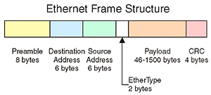
To understand why it is so important to eliminate duplicate paths, we need to examine how Ethernet frames (i.e. packets) are transmitted. Fig. 1 shows the basic structure of an Ethernet frame, consisting of a preamble, destination address, source address, EtherType code and CRC checksum. The preamble is an 8-byte pattern that indicates the start of each Ethernet data frame. Following the preamble are 6-byte destination and source addresses (known as MAC or media access control addresses) that uniquely identify each device or port on a router. The next two bytes are used for the EtherType field, which indicates the type of data contained in the frame, such as Internet protocol (IP) packets. The actual contents of the Ethernet frame follow next in a variable-length field. The four byte checksum at the end of the frame is used to verify the data in the frame.

Fig. 1: Ethernet Frame Structure Notice that there is no field or flag in the Ethernet frame format that can be used to determine if a data frame has been circulating around the network without reaching its destination. (This is in contrast with standard IP packets that have a time-to-live counter that gets decremented at each hop along its path; when the counter reaches zero, the packet is destroyed.) If there are any loops or duplicate paths in the network, then it is very easy for data frames to circulate endlessly around the network, tying up bandwidth that could be used for useful data. By connecting the network in a strict tree, loops are avoided, and data can flow easily from any source to any destination.
There is one big drawback to a strict tree structure—there is no redundancy. That is to say, with only one possible path from any source to any destination, any failure along any path means that communications will cease until the failure is repaired. For many networks, particularly those carrying live video traffic, lengthy service outages are highly undesirable. To remedy this situation, many networks have built-in redundancy, in the form of backup links or alternate routes between switches.
Unfortunately, once spare links are installed, we create loops in the network, which we were trying to avoid. To fix this, we must configure the network so that redundant links can be present in the network, but in a disabled state until they are needed. This can be done manually, but a much better way is to use STP.
BUILDING THE SPANNING TREE
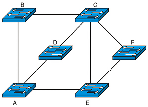
While the concept of building a tree might sound simple, the practical reality of getting dozens of devices produced by a variety of manufacturers to all cooperate requires a number of steps. Fortunately, STP is widely implemented throughout many different brands of networking equipment, and is often enabled by default in Ethernet switches. Let's take a look at the process used to build a spanning tree (called "convergence") using the network of six Ethernet switches shown in Fig. 2.
Switches in a network regularly exchange data about their configuration using messages called bridge protocol data units. These messages contain information about each switch, including the MAC address of the switch, the types of connections present on the switch (100BaseT, GigE, etc.) and information about how the switch is connected to the network root.

Fig. 2: Switch Network The first step in convergence is to identify which switch is going to act as the root node. When first turned on, each switch in the network assumes that it is the root switch in the network and broadcasts a BPDU to that effect out all of its active ports. When other switches receive this BPDU, they compare that information to their own current configuration. A score is assigned to each of the received BPDUs based on the MAC address and a user defined priority field. Whichever switch in the network has the lowest total score is elected to be the new root switch. In the case of the network shown in Fig. 2, the network administrator had selected node A to be the root by giving it priority over all the other switches in the network, and so all of the other switches will come to recognize A as the root after processing the BPDUs they receive.
Once the root is established, each switch needs to figure out a single path to the root. This is again done through the use of BPDUs. Each connection between switches is assigned a cost based on its capacity and a user-definable priority. Higher capacity connections are assigned a lower cost. These costs and priorities are then used to determine which connections are going to be used to form the tree.
Any switches that have a direct connection to the root are configured to use that connection. In Fig. 2, switches B, D, and E are all connected directly to the root node, and their connections to the root will be activated. For switch C, there are three possible paths to the root, so the costs of each path are calculated by summing the costs of the paths along the route. If the path passing through node B is the lowest cost, then the links between C and D and between C and E will be disabled. Similarly, Switch F will most likely decide that the best path to the root is via E and disable the connection to C. Once this convergence process is complete, then user data can flow over the network.
There are some very desirable aspects of STP for video networks. One important feature is that STP prevents endlessly circulating packets, which could use up bandwidth needed for video applications. Another big feature is the ability to automatically recover from a network failure. If a path or a switch fails, then the spanning tree process will run, and a new set of connections between the switches will automatically be set up.
The biggest drawback to STP is the fact that convergence takes some time to run, and while it is running, user data is not passed through the network. This applies to the entire set of interconnected switches, not just ones that have experienced a failure. Using the older version of STP (known as IEEE 802.1d), this convergence process could take up to 50 seconds. A more recent version of this process, called Rapid STP (known as IEEE 802.1w) has reduced this time to 3 to 5 seconds, or less than 1 second for many configurations. Unfortunately for video signals, even that relatively short time will take a television broadcast off the air, particularly when the recovery time of the attached equipment is added to the total. What's even worse is that STP re-convergence can also be triggered by human actions such as adding a new switch to an existing network.
LIVING WITH STP
STP is a key part of any Ethernet system, and performs some essential functions. For companies with high-performance video requirements, some policies can help minimize the negative aspects of the protocol. Small, simple networks will tend to converge more quickly than large, complex ones. Redundancy should certainly be present, but used strategically rather than trying to connect every switch to every other switch. Planned maintenance actions such as installing a new switch or removing old cabling should be scheduled for times when a short-term network outage can be tolerated. With these simple steps, STP can be a valuable part of any video network.
Wes Simpson is a consultant and author of Video Over IP, second edition, now available from Focal Press. Please feel free to contact him atwes.simpson@gmail.com.
The professional video industry's #1 source for news, trends and product and tech information. Sign up below.
Wes Simpson is President of Telecom Product Consulting, an independent consulting firm that focuses on video and telecommunications products. He has 30 years experience in the design, development and marketing of products for telecommunication applications. He is a frequent speaker at industry events such as IBC, NAB and VidTrans and is author of the book Video Over IP and a frequent contributor to TV Tech. Wes is a founding member of the Video Services Forum.

