Transmitter Sites: Things to Consider for ATSC 3.0
Many stations will replace transmitters, RF systems, line and antennas as part of the channel repack after the incentive auction and it makes sense to select gear that will work for ATSC 3.0. A move to ATSC 3.0 could be as simple as replacing the transmitter’s exciter and providing an IP link from the studio, but a system designed for ATSC 1.0 alone may not support single frequency network operation, the full ATSC 3.0 channel bandwidth or the same power level as ATSC 1.0. This month I’ll cover some of the things to consider when making changes at the transmitter site.
ATSC 1.0 provides support SFNs (also called distributed transmission systems) but they haven’t been widely used in the United States, likely because it is difficult to avoid interference between the transmitters unless they are isolated by terrain. To make matters worse, different ATSC 1.0 receivers will handle the interference differently.
With ATSC 3.0, as I’ve pointed out in earlier columns, most of those problems go away with proper selection of the OFDM guard interval. However, as with ATSC 1.0, all of the ATSC 3.0 transmitters on a channel in a SFN have to transmit exactly the same signal. Optimization of the SFN requires the ATSC 3.0 signals be emitted from each transmitter at different but precise times.
This means the signal from the studio sent to the transmitters either has to contain all the data, exactly as it is to be transmitted, or that the signal from the studio has to include enough metadata to allow each of the transmitters in the SFN to create and emit exactly the same signal.
TWO APPROACHES
The first approach essentially splits the exciter between the transmitter and the studio. This requires extra bandwidth, as all of the overhead needed to create the constellation has to be added at the studio. At the NAB Show, studio transmitter link (STL) bandwidths of up to 250 Mbps were suggested for this approach.
The second approach, currently being finalized in ATSC S32, allows sending the different program and data streams, signaling information and timing information to the transmitter in a way that the exciter at the transmitter can take all these streams, add the appropriate error correction to them, create the constellation waveform and emit a signal at the correct time that matches all the other transmitters in the SFN. This standardized approach should allow an SFN using exciters from different manufacturers.
The good news is that any microwave or fiber link that supports IP transmission should work for ATSC 3.0, but the data rate required by the first approach might be for many existing microwave STL links. The ATSC 3.0 SFN standard will help solve that problem. Either approach will require additional hardware at the studio and the transmitter site.
The good news is companies are aware of this—we saw an STL using the first approach working at the NAB Show and companies are planning support for the more efficient ATSC 3.0 SFN/STL technology.
Any transmitter that can handle ATSC 1.0 should be able to transmit ATSC 3.0 with a change of exciter. It may not, however, be able to match the output power of ATSC 1.0. The reason is that ATSC 1.0, a single carrier system, has a lower peak-to-average power ratio (PAPR) than ATSC 3.0, a multicarrier OFDM system.
A simple way to check this is to look at the specifications for the transmitter. Most transmitters sold today are offered for both ATSC (8-VSB) and DVB (COFDM) use, but the power levels are not always the same.
Comark specifies the same power levels for both modulations for its PARALLAX transmitter, as does Rohde & Schwarz for its current THU9 transmitter. However, the new Doherty amplifiers R&S showed at the NAB Show have a higher power rating for ATSC, as do GatesAir’s Maxiva “PowerSmart” transmitters. Check the datasheets for specifics and keep this in mind when specifying a replacement transmitter’s output power.
The ATSC 3.0 standard includes tools for reducing PAPR, including tone-reservation, but they can have an impact on available data bandwidth. Annex M of the ATSC Proposed Standard A/322—Physical Layer Protocol describes a peak-to-average power reduction algorithm for tone reservation and a possible one for the active constellation extension (ACE) method. Find the latest version at www.atsc.org.
IMPACT ON COMPONENTS
ATSC 3.0’s higher PAPR will also have an impact on the components at the output of the transmitter. Even if the average power is unchanged, the higher peak power will result in higher RF voltages, potentially leading to arcs and burn-out in RF system components like filters, transmission line and antennas.
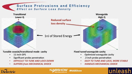
Derek Small, senior engineer with Dielectric, outlined the power handing capability of different filter designs under ATSC 1.0 and ATSC 3.0 in his NAB Show presentation, “Efficient UHF Tunable Waveguide TE10 Mode Filter.” Broadcasters want tunable filters to allow them to change channels without replacing their RF system. Most tunable filters use tunable coaxial/transitional mode cavities. They are compact compared to waveguide designs, but have greater loss.

Fig. 1: A slide from Small’s NAB Show presentation on Dielectric’s tunable waveguide filter that has lower loss than the tunable coaxial/transitional mode cavity filters and greater power handling capability. The significant probe penetration in these filters leads to higher electric field densities, making them more susceptible to breakdown with ATSC 3.0’s higher PAPR and potentially reducing the maximum power they can handle compared to ATSC 1.0.
Small and Dielectric developed a tunable waveguide filter (Fig. 1) that has lower loss than the tunable coaxial/transitional mode cavity filters and significantly greater power handling capability (Fig. 2). Henry Fries, vice president of operations with Comark, told me that the company plans to use these filters with its new Parallax transmitter.
The ATSC 3.0 COFDM signal can occupy up to 5.83 MHz of a 6 MHz channel, more than the 5.38 MHz occupied bandwidth of an ATSC 1.0 signal. Current plans for ATSC 3.0 in the United States do not change the emission mask or out-of-channel emission limits—ATSC 3.0 broadcasters will have to comply with the existing emission mask.
One way to accomplish this is to reduce the number of carriers transmitted, reducing the occupied bandwidth to 5.51 MHz. See Table 7.1 of ATSC A/322 for details. Another option is to use a more complex filter.
The same breakdown voltage concerns Small mentioned in his presentation should apply to tuners in transmission lines and parts of antennas with high electric field density. Myat has created a document that contains, among many other things, tables and formulas for calculating the average power and peak power handling capability of transmission lines. Download the PDF from www.myat.com/images/stories/pdfs/Engine.pdf. The “Peak Power Rating and Production Test Voltages” table from the document shows the peak power limit for different sized line. Note that these values are for 1:1 VSWR and do not include modulation. Peak and average power ratings will be reduced for realworld conditions!
Broadcasters looking to reach indoor antennas and portable devices will be adding elliptical polarization, increasing the amount of power in filters, transmission lines and antennas. Making sure these components can handle higher peak powers with ATSC 3.0 will help avoid costly burnouts.
The transmitter site changes required for ATSC 3.0 are small compared with those required at the studio and in viewers’ homes. With a bit of planning when changing channels for the repack or upgrading facilities, the change at the transmitter site could be as simple as loading new firmware into the exciter!
Doug Lung is vice president of Broadcast Technology, NBC/Telemundo stations. He welcomes your comments and questions. Email him atdlung@transmitter.com.
Get the TV Tech Newsletter
The professional video industry's #1 source for news, trends and product and tech information. Sign up below.

Doug Lung is one of America's foremost authorities on broadcast RF technology. As vice president of Broadcast Technology for NBCUniversal Local, H. Douglas Lung leads NBC and Telemundo-owned stations’ RF and transmission affairs, including microwave, radars, satellite uplinks, and FCC technical filings. Beginning his career in 1976 at KSCI in Los Angeles, Lung has nearly 50 years of experience in broadcast television engineering. Beginning in 1985, he led the engineering department for what was to become the Telemundo network and station group, assisting in the design, construction and installation of the company’s broadcast and cable facilities. Other projects include work on the launch of Hawaii’s first UHF TV station, the rollout and testing of the ATSC mobile-handheld standard, and software development related to the incentive auction TV spectrum repack. A longtime columnist for TV Technology, Doug is also a regular contributor to IEEE Broadcast Technology. He is the recipient of the 2023 NAB Television Engineering Award. He also received a Tech Leadership Award from TV Tech publisher Future plc in 2021 and is a member of the IEEE Broadcast Technology Society and the Society of Broadcast Engineers.
