Turned Off TV Sets Can Jam Signals

Charles W. Rhodes
My colleague Linley Gumm and I recently made an accidental discovery. When we turned our RF test bed on for a second day of testing of inter-band interference, all seven of our DTV receivers failed to come on. Some had much greater jamming than in our tests two days earlier.
I previously wrote about inter-band interference in which two or more undesired signals on the high VHF band channels generate third-order distortion products, which fall in the UHF band where they raise the noise floor under the desired ATSC signal. (See “Interband RFI: Should Stations Worry?”)
If the noise floor under the desired signal comes within 15 dB below the desired signal, reception fails due to this IBI, which has seldom been considered because the RF selectivity of receivers in the past helped protect against it. This may not be the case with the integrated circuit tuners that dominate DTV receivers today.
When Linley and I first discovered the anomaly, we had no idea why the change happened or which set of data were incorrect. We moved the spectrum analyzer to an output of the eight-way signal splitter, which feeds our seven receivers and to a HP 436 Power Meter. Wow!
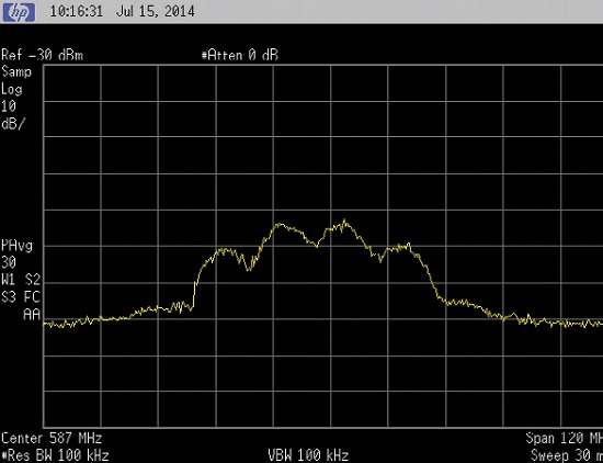
We saw third-order IM products across much of the UHF band as shown in Fig. 1. Note that the center frequency of the spectrum analyzer in Fig. 1 is 587 MHz (Ch. 3). Third-order IM “Bee-Hives” generated by Chs. 9 and 11 are centered at 579 and 591 MHz. Their third harmonics are centered at 567 and 603 MHz. That proved these spurious responses are third-order intermodulation products. So we tracked the source of the third-order distortion, which turned out to be the DTV receiver we failed to turn on.

Fig. 1: Third-order distortion products generated in a modern DTV receiver when not operating.

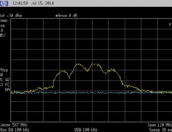
Fig. 2: Third-order distortion products generated in the input circuitry (yellow trace) of modern receivers vanish when they are not in operation vanish (blue trace) when the receiver is operational. When all seven receivers are turned on, there was nothing in the UHF band and all seven receivers displayed pictures.
Fig. 2 shows a blue trace, which is the baseline noise floor in the UHF band when all receivers were on.
When at least one receiver was off, the distortion products appeared (yellow trace). Somehow, a receiver, when off, can generate third-order distortion products, which travel back through the signal splitter to the other receivers also connected to this signal splitter. Those receivers were jammed by these distortion products. When all receivers were on, no third-order distortion products were generated. All receivers worked.
When a modern receiver is off, its RF input impedance is not 75 ohms, so the coax from the signal splitter is not properly terminated. We suspect the third-order distortion products were generated in the front end of the off receiver. With the receiver “dead,” there would be no back bias voltage applied to junctions of diodes or the RF amplifier transistor, so our VHF signals drive the unbiased junction in conduction.
If this is true, then the “off” receiver looked like a highly nonlinear load (the conducting junction) to the coax cable. Of course, the “on” receivers received the third-order distortion products (IM3, third harmonics and Triple Beats) being generated in the “off” receiver. These fell in Chs. 32 and 34. We had tuned all seven receivers earlier to Ch. 32.
Where three or more strong high VHF band signals are received, there will also be Triple Beats (TB) generated in an off receiver. There are 31 Triple Beats generated by all seven high VHF signals. The lowest TB is 177 MHz + 183 MHz + 189 MHz = 549 MHz, Ch. 25.
The highest TB is generated by signals on Chs. 11, 12 and 13. The sum of their center frequencies is 621 MHz. The highest frequency in this spectrum is 627 MHz in Ch. 40. Third harmonics of high VHF band signals are 3* 177 MHz – 9 MHz = 522 MHz. The highest third harmonic is 3* 213 MHz + 9 MHz = 648 MHz Ch. 43.
Third-order distortion products are generated in a receiver when not operating. Which UHF TV channels could be jammed by two high VHF band signals?
The lowest channel pair is Chs. 7 and 8. The center frequency of Ch. 7 = 177 MHz, and for Ch. 8; 183 MHz. The center frequencies of the IM3 for this pair is 2* 177 = 354 + 183 = 537 MHz. This is in Ch. 25 (536 – 542 MHz. The lowest frequency component of this IM3 is 9 MHz lower: 528 MHz, which is in Ch. 23.
Likewise, the highest frequency of this IM3 is 2*213 + 207 = 633 MHz (center frequency). Adding 9 MHz to get the highest frequency component, we get 642 MHz, which lies in Ch. 42. Most of these channels are those most likely to remain TV channels after re-packing next summer.
Why is this accident worth writing about? Consider that many homes having a rooftop antenna are receiving signals from that antenna via a signal splitter. Now consider that one receiver is tuned to a UHF channel, say 32 or 34, while a pair of strong VHF signals, say on Chs. 9 and 11, are also feeding both receivers. If one of these receivers is “off” the other may not be able to receive the desired UHF channel (32 in this example). It is possible that someone sooner or later would stumble across the fact that one receiver was “off” when the other receiver could not receive Ch. 32 or 34.
In a second scenario, the rooftop antenna is feeding multiple apartments in the same building. In this scenario it would be nearly impossible to determine the cause of erratic reception of the UHF channel.
Many, if not most, homes today receiving TV signals with a rooftop antenna have at least two receivers connected to the antenna by means of a signal splitter. If one of these receivers is off, and the other is on, and tuned to a weak UHF signal, it may not work reliably. That is, it may be getting interference generated by the off receiver’s front end. Apartment houses, hotels etc. have a master antenna and distribution amplifiers to compensate for the attenuation of the signals by signal splitters.
Very strong high VHF band signals can cause interference to receivers tuned to many weak UHF signals. So this form of Inter-Band Interference is indeed real. I deemed this hitherto little known interference mechanism worth writing about because I expect it will be an annoyance to OTA viewers after channel re-packing.
Stay tuned for more good news.
Charles Rhodes is a consultant in the field of television broadcast technologies and planning. He can be reached via e-mail atcwr@bootit.com.
Get the TV Tech Newsletter
The professional video industry's #1 source for news, trends and product and tech information. Sign up below.
