Unanticipated Interference After Repack
In my April column (“Auction Over, Now Let’s Assess the Damage”), I wrote about the damage in terms of unanticipated (by the FCC) interference to DTV reception after the repacking of the 600 MHz band.
The FCC has noted that there will be very little additional interference after repacking. Their studies examine both co-channel (CCI) and adjacent channel interference (ACI). There are other kinds of interference known, but the FCC does not consider these in its calculations.
I am referring to interference to DTV reception by certain pairs of undesired signals that generate third-order intermodulation products, which happen to fall into the desired channel and to certain triplets of undesired signals that generate triple beats whose spectrum overlaps the desired channel. My April column explained these additional kinds of interference.
THE CHICAGO EXAMPLE
Recently the FCC published the list of TV channel allotments following its repacking of the UHF channels. Now we can assess the likelihood of such interference as may be found within about three years when all stations will be operating on their new channels.
I chose stations in Chicago as examples. You can follow my calculations for your station in your community by emulating my example.
First, the FCC chose its “Scenario No. 7” as the basis for reallocating stations in the 600 MHz band. This is shown in Fig. 1.
Fig. 1: FCC Scenario 7—The Frequency Planning Basis of the 600 MHz Band

Click on the Image to Enlarge
The UHF TV spectrum extends from Channel 14 to and including Channel 36. The spectrum sold to broadband operators extends from Channel 38 to and including Channel 51. This spectrum is 35 MHz wide and was sold in blocks of 5.0 MHz each. Some broadband operators now own two or more contiguous blocks. The power of a 15 MHz block is yet to be determined, but the power limit for two contiguous blocks will be 3 dB higher than for a 5.0 MHz block, so the radiated LTE signal power density (watts per MHz) is constant between 5, 10 and 15 MHz emissions from base stations.
If the FCC were to hold all LTE signals to the same radiated power then the coverage of a 5 MHz system would exceed the coverage of a 10 or 15 MHz system. This is because receivers for LTE signals must have the same bandwidth as the signal from the base stations with which they communicate.
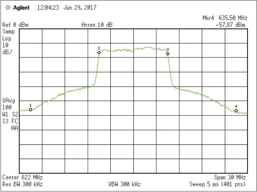
Fig. 2: Mkr. 1 608.5 MHz; Mkr. 2 617.5 MHz; Mkr.3 626.5 MHz; Mkr. 4 635.5 MHz
Assume that these LTE signals are 5 MHz wide each. If one of these overloads a DTV receiver near a base station, third-order distortion products will spread to be 15 MHz wide. Likewise, if a 10 MHz LTE signal overloads a DTV receiver, the LTE signal will be spread over 30 MHz; 10 MHz will be below the LTE signal and 10 MHz will be above the LTE signal. (See Fig. 2.) A 15 MHz wide LTE signal will spread out over 45 MHz.
You may wonder why all LTE signals are not 5 MHz wide. The answer is that in a second auction successful bidders in the first auction now owning two or more 5 MHz blocks can and will combine them into what I call a “super block” of 10, 15 or even 20 MHz width.
You might think that broadband systems would all start off with 5 MHz LTE signals, increasing their bandwidth as the business grows. But that would make all the cell phones in service obsolete. So I expect that systems will start up with all the bandwidth they now own.
Systems on the air in three years can be 5, 10, 15 or even 20 MHz systems. It also means that when they start radiating at their maximum power allowed, whatever interference results will be immediately evident if this interference blocks DTV reception near a base station.
CHANNEL 37
Now suppose that an LTE signal is 10 MHz wide as in Fig. 2. The signal occupies blocks A and B (617–627 MHz). If it overloads a receiver, third-order products will extend 9 MHz below block A to 606.5 MHz below block A (617–622 MHz), and third-order products will also extend 9 MHz above block B up to 636.5 MHz.
In Fig. 1, we see that Channel 37 is between 608–614 MHz. Channel 37 is used for medical telemetry in U.S. hospitals. However, base stations transmitting on both blocks A and B (617–627) may jam Channel 37 transmissions if the base station signal overloads nearby hospital receivers.
The situation with a 5 MHz LTE signal on block A is quite different. Third-order distortion products from block A only fall between about 614 and 617 MHz so there is very little noise in Channel 37 from a 5 MHz wide LTE signal on block A, and there is no noise in Channel 37 from a 5 MHz LTE signal on other blocks.
The FCC wisely provided a guard band between 614 and 617 MHz. But this is too small a guard band where a 10, 15 or 20 MHz LTE is deployed because the third-order distortion spectrum extends further downwards from 617.5 MHz into the TV spectrum.
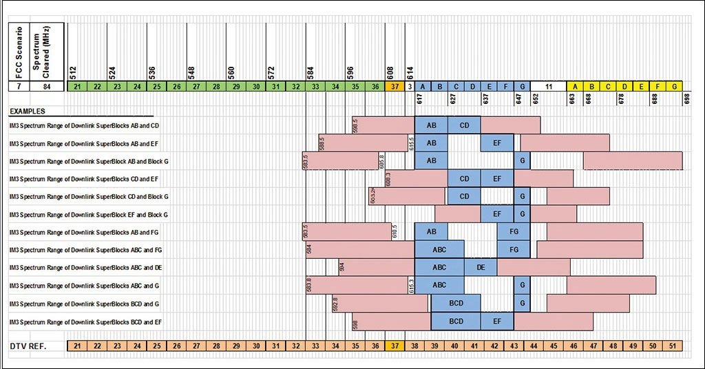
Fig. 3: Twelve examples of the third-order interference spectrum products generated by pairs of downlink LTE blocks
Click on the Image to Enlarge
Fig. 3 (courtesy of my colleague Stanley Knight), shows the spectrum spreading for various combinations of undesired signals at the frequencies (shown vertically); the spectrum ends in a TV channel. However, the power per MHz (spectrum density) rolls off sharply as the frequency approaches zero power.
An interesting case would be with one 5 MHz LTE on block A and a second LTE on block G. It can be shown that third-order distortion products would be found centered at 590 MHz, Channel 34. I believe that this unanticipated interference will be to Channels 33–36. Channels below 34 will also be subject to interference of this kind from an undesired ATSC signal and a base station or by signals on certain pairs of DTV channels pairs.
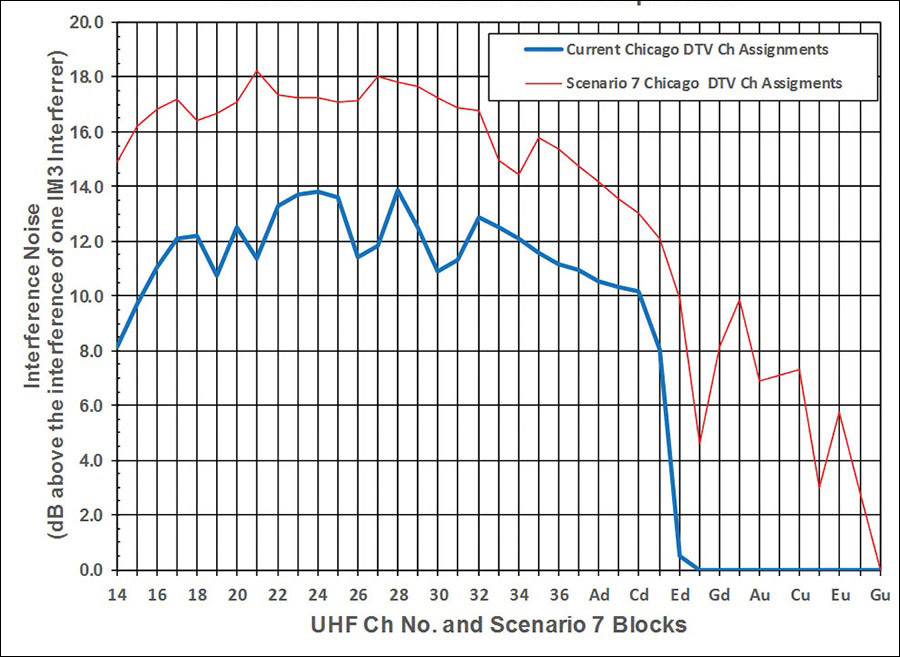
Fig. 4: Current and repack Chicago DTV assignments and their interference noise due to IM3 and triple beats
In Figs. 4 and 5, Knight plotted the situation that will exist in Chicago, after the repacking and all stations are at full power. He took into account the third-order distortion products, not only from base station emissions, but also the TV signals.
In Fig. 4, Knight compares the interference (noise) in Chicago today in blue with the noise after repacking in red. This demonstrates the effect of packing signals closer, which is what repacking is all about. Note that there is no noise now above block E. This is the downlink signal from base stations. That changes after repacking.
At some sites, receivers may be overloaded by the combination of base station signals and remaining TV signals in the 600 MHz band. Fig. 4 indicates that the noise level increases by about 6 dB with repacking. And it also extends the noise power spectrum across Channel 37 by about 5 dB. There is no noise above the highest base station downlink frequency Ed.
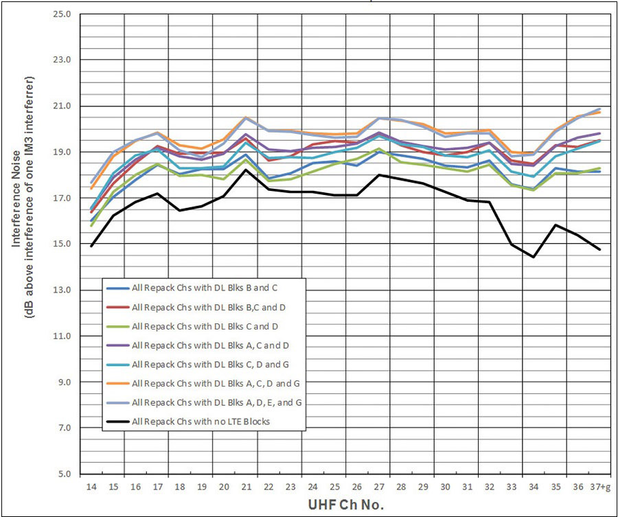
Fig. 5: Scenario 7—Chicago repack and broadband block interference noise due to IM3 and triple beats
Fig. 5 compares the interference noise for a number of downlink base station blocks, so it is clear that this interference—when you take into account both downlink base station and cell phone (uplink) emissions and TV signals—extends across the 600 MHz TV band.
Closing on a cheerful note, these unanticipated signals can be kept out of receivers by means of a low pass 75 ohm filter, which passes signals on and below Channel 36. That is how this problem is dealt with in Europe.
Charles Rhodes is a consultant in the field of television broadcast technologies and planning. He can be reached via e-mail atcwr@bootit.com.
For more information on the repack, visit TV Technology's repack silo.
Get the TV Tech Newsletter
The professional video industry's #1 source for news, trends and product and tech information. Sign up below.
