Verifying TV Facility Coverage
This month I’ll wrap up coverage of papers at the IEEE Broadcast Symposium as part of a discussion about measuring the coverage of existing or new facilities installed as part of the FCC channel repack.
THE CHALLENGE
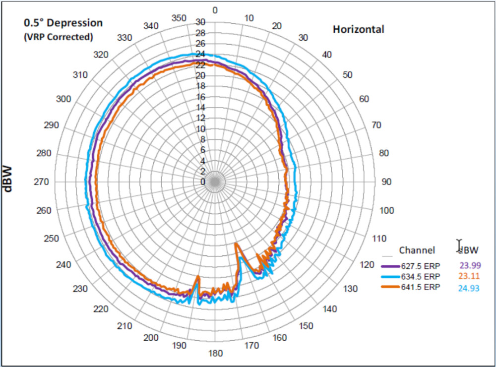
Fig. 1: A tower 650 feet away created a 3 dB notch in the antenna pattern.

Click on the Image to Enlarge
Since the beginning of broadcasting, stations and their engineers have looked for ways to verify their signal was actually reaching the audience. Aside from viewer surveys, field measurement of signals on the ground was the only option for these pioneer TV stations.
The size of receive equipment using vacuum tubes and the need to get the antenna high enough to match the outdoor antenna heights used by most viewers at that time mandated specially designed vehicles for these measurements.
[IEEE Broadcast Symposium Part 1: Repack]
Anyone who has done field measurements, whether with a sophisticated measurement van or just a field strength meter, a pole and a TV antenna, has seen that the surroundings and antenna height greatly impact the signal level.
The FCC recognized this in the measurement method specified in “Field Strength Measurements,” Section 73.686 of the FCC rules. After describing selection of measurement locations and antenna orientation, it states, “(v) A mobile run of at least 30.5 meters (100 feet) is made, which is centered on the intersection of the radial and the road, and the measured field strength is continuously recorded on a chart recorder over the length of the run.” In an area with power lines, this could be difficult, if not downright dangerous!
I’ve come up with some alternative methods of on-the-ground measurements, which I’ve described in previous columns. One uses an antenna on a 10–12 foot pole able to be stored in a conventional vehicle with measurements taken in a circle with points as close to the same distance from the transmitter site as possible. Due to the location variability noted above and measurement location availability, absolute field strength readings may be unreliable, but at least they can be compared with other stations on nearby channels at the same antenna farm.
Another method is to take hundreds of measurements on the ground using a vehicle with multiple antennas at different orientations designed to be able to grab readings from a dozen stations or more from each of the antennas in less than 10 minutes per location. This is the method used in New York City to check reception from One World Trade Center prior to installation of the master antenna. The main purpose of this study was to verify reception as measured by signal lock and SNR on the different antennas rather than precisely measure received channel power and field strength.

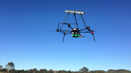
The Cavell-Mertz drone has a custom Tarot-brand frame with six motors and a custom flight controller with inertial sensors.
All of the methods described above show reception only at specific points, which may be affected by structures on the ground. A different approach is to measure the pattern of the antenna, as precisely as possible, then use that as input to propagation software such as the FCC’s TVStudy, V-Soft’s Probe, Progira’s PROGIRA plan, LS Telcom’s CHIRplus or John Magliacane’s free SPLAT to predict signal level at any location. The question then becomes, how do we measure the real antenna pattern once it’s on the tower?
DRONES TO THE RESCUE
Over the past 30 years I’ve worked with engineers from Hammett and Edison to do antenna measurements from both helicopter and fixed wing aircraft. Helicopter measurements allowed the vertical drops needed to measure elevation patterns, but were very expensive and only suitable for locations without flight restrictions, blocking access to areas around the antenna.
Click on the Image to Enlarge
Fixed wing measurements are less expensive but, except for certain mountaintop sites, elevation pattern measurements are difficult if not impossible.
Unmanned aerial vehicles offer the flight flexibility, high location precision (through GPS-based flight path control) and the ability to operate at heights low enough to measure an antenna’s elevation pattern. Two papers at the IEEE Broadcast Symposium showed how drones could be used to verify antenna performance.
The presentation “Antenna Pattern Measurement With a Drone,” by John Kean at Cavell, Mertz and Associates, provided an excellent overview of the many items that have to be considered. The Cavell-Mertz drone has a custom Tarot-brand frame with six motors and a custom flight controller with inertial sensors for trim, a flux-gate compass for orientation and a differential GPS that provides autonomous flight over a pre-defined path. RF hardware includes a biconical broadband antenna, wireless telemetry and a custom software-defined receiver for measurements. Everything has to be RF shielded to handle the high field strength (over 20 volts/meter) found at tower sites.
Kean cautioned that accurate measurements require flight in the far field of the antenna array. Ground reflections also have to be considered. In his presentation he showed these could cause signal variations from +6 to –25 dB! Careful post-processing of the data is necessary to reduce sampling noise and convert positional information. Kean’s presentation is available to IEEE Broadcast Symposium attendees in the proceedings. Copies may be available through John Kean and Cavell-Mertz at www.cavellmertz.com.
[IEEE Broadcast Symposium Part 2: Antennas]
Ian Gair, from Sixarms, echoed many of Kean’s cautions in his presentation “Real World Results for a Signal Measurement Drone.” Gair provided a “rule of thumb” for determining the far-field distance for drone measurements: 450 feet for large FM arrays, 1,200 feet for VHF-TV and 1,800 feet for UHF-TV.
Gair provided several examples of antenna issues uncovered with drone measurements. These included an inverted panel in a panel array, a panel oriented incorrectly, antenna tilt due to storm damage and severe elevation pattern distortion caused by incorrect feeder phasing.
Fig. 2: The impact on the antenna pattern of structures at 170 and 540 feet.

The items I found most interesting were the impact of surrounding towers on the antenna pattern. Fig. 1 shows a tower 650 feet away created a 3 dB notch in the antenna pattern. Another example, shown in Fig. 2, shows the impact of structures 170 feet away at 160 degrees and another 540 feet away at 190 degrees. They caused 7 and 4 dB notches, respectively.
For more information on Sixarms drone measurements or to obtain a copy of the presentation, visit the
company’s website at www.sixarms.com.
CHOICES
We’ve become used to thinking of our actual antenna patterns like those plotted on the antenna manufacturers’ datasheets. Traditional ground measurements had so much variability due to obstructions and a limited number of measurement points that even relatively large pattern discrepancies of 3 dB might not be noticed.
The ability to quickly and accurately measure real antenna patterns using drones lets us see the real performance of our antennas and—perhaps more troubling since there may be nothing that can be easily done to fix it—the impact of the surrounding structures on antenna performance.
Signal measurements are a reimbursable expense for stations participating in the FCC incentive auction channel repack and I suspect many broadcasters checked that box on their Form 399. The question now is whether to use a drone to verify antenna performance, use a test vehicle to do traditional on-the-ground radial measurements or a combination of both. What are your station’s plans for post repack measurements?
As always, your comments and questions are welcome. Email me at dlung@transmitter.com.
Get the TV Tech Newsletter
The professional video industry's #1 source for news, trends and product and tech information. Sign up below.

Doug Lung is one of America's foremost authorities on broadcast RF technology. As vice president of Broadcast Technology for NBCUniversal Local, H. Douglas Lung leads NBC and Telemundo-owned stations’ RF and transmission affairs, including microwave, radars, satellite uplinks, and FCC technical filings. Beginning his career in 1976 at KSCI in Los Angeles, Lung has nearly 50 years of experience in broadcast television engineering. Beginning in 1985, he led the engineering department for what was to become the Telemundo network and station group, assisting in the design, construction and installation of the company’s broadcast and cable facilities. Other projects include work on the launch of Hawaii’s first UHF TV station, the rollout and testing of the ATSC mobile-handheld standard, and software development related to the incentive auction TV spectrum repack. A longtime columnist for TV Technology, Doug is also a regular contributor to IEEE Broadcast Technology. He is the recipient of the 2023 NAB Television Engineering Award. He also received a Tech Leadership Award from TV Tech publisher Future plc in 2021 and is a member of the IEEE Broadcast Technology Society and the Society of Broadcast Engineers.
