What You Need to Know About Adjacent Channel Interference

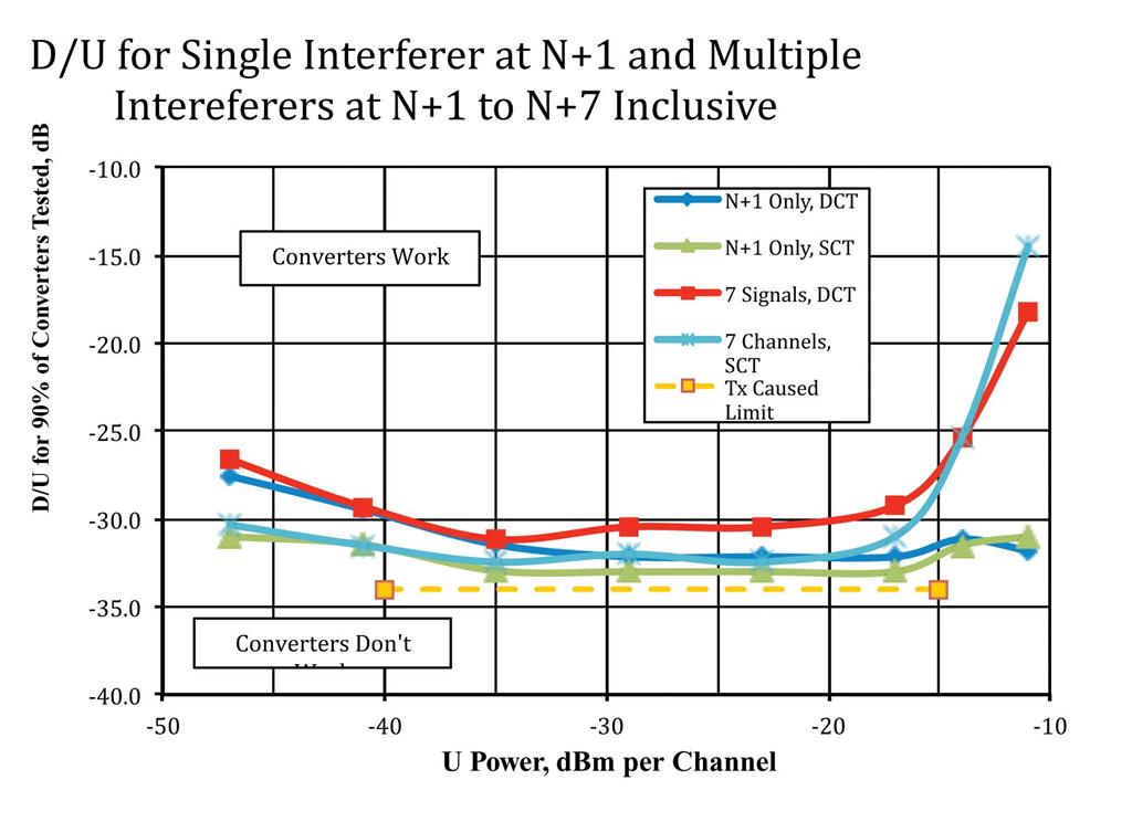
Fig. 1: Desired-to-Undesired threshold of NTIA-approved digital-to-analog TV converter boxes measured for a wide range of undesired signal powers. The yellow trace was computed based on the transmitter nonlinearity permitted under current FCC rules.
Adjacent channel interference between DTV signals may become critical after the FCC repacks the remaining UHF TV spectrum. Up to 120 MHz of UHF TV spectrum down from Ch. 51 may be re-allocated to broadband in the upcoming spectrum incentive auction.
Congress wrote the auction legislation around the notion that only spectrum voluntarily surrendered by broadcasters will become available. Broadcasters could be left with as few as 15 UHF channels. That will be like packing sardines in a can, very tight packing indeed. Many broadcasters will be sandwiched between two or more other broadcasters.
GETTING FROM U TO D
To investigate how this could play out, Linley Gumm and I modified our radio frequency test bed, which provides one or two undesired (U) ATSC signals to seven undesired ATSC signals on Chs. 30, 31, 32, 33, 34, 35 and 36. We have run tests with the desired (D) ATSC signal on Ch. 29. Each U signal is uncorrelated with all others just as it would be in the real world.
The mechanism by which the U signal gets transferred to the D signal is unique to adjacent channel interference, or ACI, and not widely understood. The ATSC standard specifies the intermediate frequency selectivity of such receivers so that ACI does not result from poor intermediate frequency filtering.
What causes ACI is the fact that a DTV signal radiated on an adjacent channel to the D signal includes nonlinear distortion products generated in the power amplifier stage(s) of the transmitter. All DTV transmitters (ATSC, DVB-T and ISDB-T), generate these nonlinear distortion products. This is why the FCC requires a costly and large DTV RF mask filter on the output of every ATSC transmitter including digital low-power transmitters and translators.
However some of these distortion products generated within the transmitter escape and are radiated.
Several authors have calculated the maximum power permitted to escape and radiate in each adjacent channel. (See “Interference to DTTV Reception by First Adjacent Channels,” IEEE Transactions on Broadcasting, March 2005, V. 51, No. 1, p. 30.) This is 44.7 dB below the power being radiated within the U channel. Much of this is within the first 0.5 MHz of the D channel where it is further attenuated by the receiver’s raised cosine IF filter.
These noise-like distortion products are seen by the DTV receiver as an increase in the noise floor under the D signal. The noise in the D channel is therefore limited by the DTV RF mask to –44.7 dB below the U power received on an adjacent channel. Subtract 1.8 dB (the receiver selectivity) and you get –46.5 dB below the received U signal power. The FCC also limits the field strength of U signals on adjacent channels to the D signal within the noise-limited coverage area of the D station to a D/U of –27 dB +/- 1 dB. This is how it protects against ACI in Table 5A of FCC OET-69, the regulation defining signal strength for defined coverage areas.
NEAR THE PERIMETER
Let’s see how this works. First we had in our RF test bed a D ATSC signal on Channel 29, and an U ATSC signal on Ch. 30. In this case the D/U limit is –26 dB.
Let’s assume that the U signal on Ch. 30 is received at –40 dBm. We deliberately overloaded an amplifier through which this U signal passes and adjusted the overload to simulate the sideband splatter of a real DTV transmitter. This puts noise in D signal at –86.5 dBm at the RF input of each NTIA-approved digital-to-analog TV converter box.
The only other significant noise source, assuming no other interferers, is the receiver-generated noise power, which is about –99 dBm. If we add these two noise powers, the result is the noise floor under the D signal of –86.29 dBm. The minimum signal-to-noise ratio required to demodulate the ATSC signal is 15.2 dB so the minimum usable D signal power is –71 dBm.
Without this ACI the noise-limited signal power is –84 dBm. This means that we have desensitization of 13 dB due to the worst case ACI. Table 5A does not take up the possibility of two undesired adjacent channels, but it is easy to grasp that the desensitization would increase by up to 16 dB.

In analyzing the off-air signals at my laboratory, it appears that most of them are operating several decibels better than the FCC limit. We understand that ACI results from the legally radiated sideband splatter generated in the U transmitter and which escaped the mask filter. And we understand why some stations cannot be received near their noise-limited perimeter. What can be done about this de-sensitization? Engineers specializing in the design of DTV RF mask filters say that with more sections of the filter there would be somewhat less sideband splatter escaping and being radiated, but this is a very costly solution. Few stations would care to bear this expense, which only benefits a competitor or two.
The FCC made reasonable compromises in setting its current RF mask requirements.
We have proven this theory that ACI is due to the radiated sideband splatter in our laboratory. In Fig. 1 the blue trace shows the measured D/U as a function of the U power for the U signal on channel N+1. The yellow trace is computed on the assumption that the only noise source (other than receiver-generated noise) is that of the sideband splatter from the U transmitter, which is radiated. The blue (measured) trace closely approaches the theoretical limit (yellow trace).
The slight tilt where the U power is below –35 dBm is due to the receiver-generated noise, which then contributes significantly to the noise floor under the D signal. Four of the NTIA-approved converter boxes have a tuner of the double conversion-type. Their performance is shown in the green trace for N+1 only. The curve for the single conversion tuners is shown in red. Both the single conversion tuner units and the double conversion tuners tested about the same for the N+1 only tests.

We also tested these same units with the set of seven U signals. When those U signals were each above –14 dBm per channel, the total U power overloaded both kinds of units. Nevertheless, all units performed very well at and below a U power per channel of –14 dBm. At the few sites where U power per channel exceeds –14 dBm, there could be interference, but this could be eliminated with a suitable 75 ohm attenuator.
It should also be noted that these curves embrace the best 90 percent of the units tested, which is the usual criteria for interference limited reception.
This test result is the first of many planned. What it demonstrates is that extremely tight packing of ATSC signals may prove to be practical. If so, we can realize 100 percent spectrum efficiency as ATSC signals can occupy contiguous channels if all transmitters are co-sited. For example, with analog TV signals, the high VHF band of seven channels could support no more than four analog TV signals on odd Chs. 7, 9, 11, and 13; only three if the channel numbers are even, 8, 10 and 12. We could load all seven high VHF channels with ATSC signals if their transmitters are co-sited. If this works for the present ATSC signal, it should also work with whatever the ATSC proposes as the next generation of DTV for North America.
Further testing will be needed to prove this concept and we are continuing testing to prove that such tight packing of ATSC signals is possible. Next month, test results for seven ATSC U signals on Chs. N+2 to N+8 will be reported. Stay tuned.
Charlie Rhodes is a consultant in the field of television broadcast technologies and planning. He can be reached via e-mail at cwr@bootit.com
Get the TV Tech Newsletter
The professional video industry's #1 source for news, trends and product and tech information. Sign up below.
